By TNL: GN22-0498
ing, and other system-related functions.
The: physical makeup of the
various models of the
but the logical function remains the same. The result
of executing a valid instruction is the same for each
modeL
binary integers and floating-point numbers of fixed
length, decimal integers of variable length, and logi
cal information of either fixed or variable length.
of the processing elements, the multiplicity of the
shifting paths, and the degree of simultaneity in per
forming the different types of arithmetic differ from
one
results.
Instructions which the
classes: system-control, general, decimal, floating
point, and input/output instructions. The system
control and input/output instructions are privileged
instructions that can be executed only when the
tions are used in performing fixed-point, logical,
branching, and other control and data-manipulation
operations. The decimal instructions operate on data
in the decimal format, and the floating-point instruc
tions on data in the floating-point format.
To perform its functions, the
amount of internal storage other than main storage.
Portions of this storage can be designated. by the
program, such as the current program status word
isters, the control registers, the prefix register, and
registers associated with the timing facilities.
The current
control instruction sequencing and to hold and indi
cate the states of the system in relation to the pro
gram currently being executed. Registers associated
with the timing facilities
clock:, the clock comparator, and the
genelral, floating-point, and control registers are dis
instruction operation code determines which type of
register is to be used in an operation.
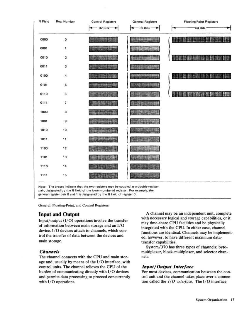
General Registers
The
registers. The general registers can be used as base
address registers and index registers in address arith
metic and as accumulators in general arithmetic and
and are designated by a four-bit R field in an instruc
tion (see accompanying illustration).
tions provide for addressing multiple general registers
by having several R fields.
For some operations, two adjacent general regis
ters are coupled together, providing a 64-bit format.
In these operations, the program must designate an
even-numbered register, which contains the high
order bits. The next higher numbered register con
tains the low-order bits.
In addition to their use as accumulators in general
arithmetic and logical operations, 15 of the 16 gen
eral registers are also used as base-address and index
registers in address generation. In these cases, the
registers are designated by a four-bit B field or X
field in an instruction. A value of zero in the X or B
field specifies no index or base is to be applied, and,
thus, general register
taining an index or base address.
Floating-Point Registers
Four floating-point registers are available for
floating-point operations. They are identified by the
numbers
floating-point register contains 64 bits and can con
tain either a short (32-bit) or a long (64-bit) floating
point operand. A short operand occupies the high
order bit positions of a floating-point register. The
low-order portion of the register is ignored and re
mains unchanged in arithmetic calling for short ope
rands. Two pairs of adjacent floating-point registers
can be used for extended operands: registers
and registers 4,6. Each of these pairs provides a 128-
bit format.
Control Registers
The
bit positions in length. The bit positions in the regis
ters are assigned to particular facilities in the system,
such as program-event recording, and are used either
to specify whether an operation can take place or to
provide special information required by the facility.
necessarily provided which are required by the in
stalled facilities.
The control registers are identified by the num
bers
the instructions
dressed by these instructions.