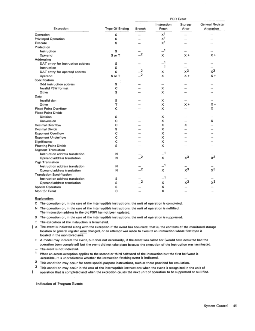
PER Event
Exception Type Of Ending S Branch Instruction Fetch
Storage Alter Operation Privileged Operation
Execute
Protection Instruction Operand OAT entry for instruction address Instruction OAT entry for operand address Operand Specification Odd instruction address Invalid PSW format Other Data I nvalid sign Other Fixed-Point Overflow Fixed-Point Divide
Division
Conversion Decimal Overflow Decimal Divide
Exponent Overflow Exponent Underflow Significance
Floating-Point Divide
Segment Translation I nstruction address translation Operand address translation Page Translation I nstruction address translation Operand address translation Translation Specification I nstruction address translation Operand address translation Special Operation
Monitor Event Explanation: S S S SorT S S S SorT S C S S T
C S C
C S C
C
C S N
N
N
N S S S C
2
2
2
2
2
x
X
X
X
X
X
X
X
X
X
X
X
X
X
X
X
1
1
1
X
X
1
X
X
X
C
The operation or, in the case of the interruptible instructions, the unit of operation is completed. N
The operation or, in the case of the interruptible instructions, the unit of operation is nullified. The instruction address in the old PSW has not been updated. S The 9peration or, in the case of the interruptible instructions, the unit of operation is suppressed.
T The execution of the instrL!ction is terminated.
X+
X3
X+
X+
X General Register Alteration X+
X3
X+
X+
X
X
X The event is indicated along with the exception if the event has occurred; that is, the contents of the monitored storage location or general register changed, or an attempt was made to execute an instruction whose first byte is located in the monitored area.
+ A model may indicate the event, but does not necessarily, if the event was called for (would have occurred had the
operation been completed) but the event did not take place because the execution of the instruction was terminated.
The event is not indicated.
When an access exception applies to the second or third halfword of the instruction but the first halfword is accessible, it is unpredictable whether the instruction-fetching event is indicated.
2 This condition may occur for some special-purpose instructions, such as those provided for emulation. 3 This condition may occur in the case of the interruptible instructions when the event is recognized in the unit of
operation that is completed and when the exception causes the next unit of operation to be suppressed or nullified. Indication of Program Events
System Control 45
Direct Control
The direct-control feature provides two instructions,
READ DIRECT and WRITE DIRECT, and an
external-signal facility, consisting of six external
interruption lines. This feature operates indepen­
dently of the facilities for performing I/O operations.
The read and write instructions provide for the
transfer of a single byte of information, normally for
controlling or synchronizing purposes, between two
cable-connected processing units or a cable­
connected processing unit and external devices. Each
of the six external lines, when pulsed, sets up the
conditions for an external interruption.
Note: Some models provide the external-signal facili­
ty as a separate feature (without the READ DIRECT
and WRITE DIRECT instructions).
For a detailed description of direct control, see
the System/360 and System/370 Direct Control
and External Interruption Features--Original
Equipment Manufacturers' Information, GA22-
6845.
Time-of-Day Clock
The time-of-day clock provides a consistent measure
of elapsed time suitable for the indication of date
and time. The cycle of the clock is approximately
143 years.
In an installation with more than one CPU, de­
pending on the model, each CPU may have a sepa­
rate time-of -day clock, or more than one CPU may
share a dock. In all cases, each CPU accesses a sin­
gle clock.
Format
The time-of -day clock is a binary counter with a
format as shown in the following illustration. The bit
positions of the clock are numbered 0 to 63, corre­
sponding to the bit positions of an unsigned fixed­
point number of double precision. Time is measured
by incrementing the value of the clock, following the
rules for unsigned fixed-point arithmetic. c. ___ o 31 32 52
In the basic form, the clock is incremented by
adding a one in bit position 51 every microsecond.
46 System/370 Principles of Operation
63
In models having a higher or lower resolution, a dif­
ferent bit position is incremented at such a frequen­
cy that the rate of advancement of the clock is the
same as if a one were added in bit position 51 every
microsecond. The resolution of the time-of -day
clock is such that the incrementing rate is compara­
ble to the instruction execution rate of the model.
When more than one time-of -day clock exists in a
configured system, the stepping rates are synchro­
nized such that all time-of-day clocks in the configu­
ration are incremented at the exact same rate.
When incrementing of the clock causes a carry to
be propagated out of bit position 0, the carry is ig­
nored, and counting continues from zero on. The
program is not alerted, and no interruption condition
is generated as a result of the overflow.
The operation of the clock is not affected or in­
hibited by any normal activity or event in the sys­
tem. The clock runs when the CPU is in the wait or
stopped state, or in the instruction-step, single-cycle,
or test mode, and its operation is not affected by CPU, initial-CPU, program, initial-program, or
system-clear resets or by the IPL procedure. De­
pending on the implementation, the clock mayor
may not run with the CPU power off.
States
The following states are distinguished for the time­
of -day clock: set, not set, stopped, error, and not
operational. The state determines the condition code
set by STORE CLOCK. The clock is said to be run­
ning when it is in either the set or not-set state.
The clock is in the not-operational state when its
power is down or when it is disabled for mainte­
nance. It depends on the model if the clock can be
placed in this state.
When the power for the clock is turned on, the_
value of the clock is set to zero, and the clock enters
the not-set state. With the clock in this state, STORE CLOCK causes condition code 1 to be set.
The clock enters the stopped state when SET CLOCK causes the clock's contents to be set, that
is, when SET CLOCK is executed without encoun­
tering any exceptions and with the TOD-clock
switch in the enable-set position. The clock can be
placed in the stopped state from the set, not-set, and
error states. The clock is not incremented while in
the stopped state. When the clock is in the stopped
state, STORE CLOCK causes the value of the
stopped clock to be stored and condition code 3 to be
set. This is distinguished from the not-operational
state, where condition code 3 is set and a value of
zero is stored.
The clock enters the set state only from the
stopped state. This is under control of the time-of-day
Previous Page Next Page