3850 3850 Mass Storage System
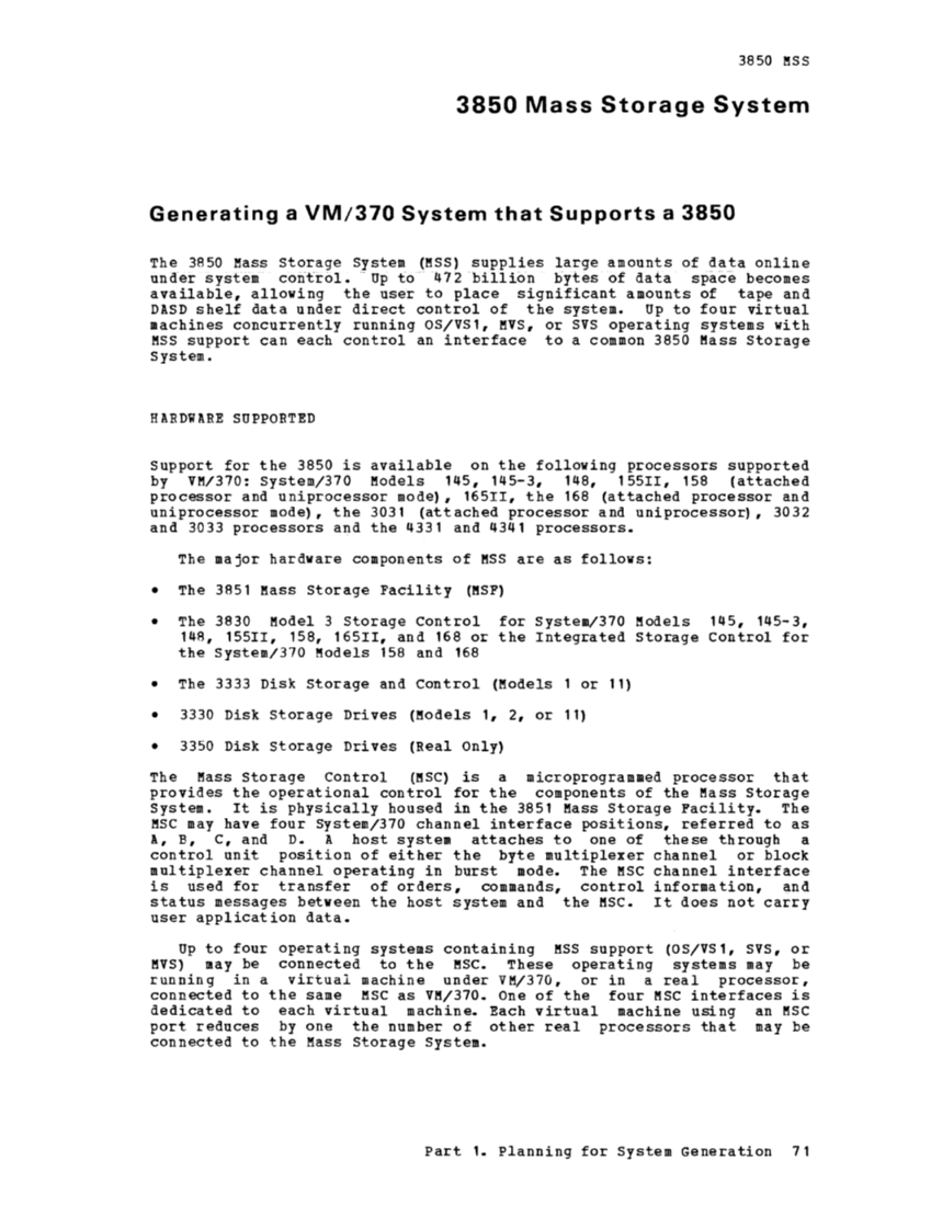
Generating a VM/370 System that Supports a 3850 The 3850 Mass storage System supplies large amounts of data online under-system coritrol.- Up to ·47 2 billion bytes of data space becomes
available, allowing the user to place significant amounts of tape and
DASD shelf data under direct control of the system. Up to four virtual
machines concurrently running OS/VS1, MVS, or SVS operating systems with support can each control an interface to a common 3850 Storage
System. HARDWARE SUPPORTED Support for the 3850 is available on the following processors supported
by VM/370: system/370 145, 145-3, 148, 155II, 158 (attached
processor and uniprocessor mode), 16511, the 168 (attached processor and
uniprocessor mode), the 3031 (attached processor and uniprocessor), 3032 and 3033 processors and the 4331 and 4341 processors.
The major hardware components of MSS are as follows: The 3851 Mass Storage Facility (MSF) The 3830 Model 3 Storage Control for System/370 145, 145-3, 148, 15511, 158, 16511, and 168 or the Integrated Storage Control for
the System/370 158 and 168 The 3333 Disk Storage and Control (Models 1 or 11) 3330 Disk storage Drives 1, 2, or 11) 3350 Disk storage Drives (Real Only) The Storage Control (ftSC) is a microprogrammed processor that
provides the operational control for the components of the Storage
System. It is physically housed in the 3851 Mass Storage Facility. The MSC may have four System/370 channel interface positions, referred to as
A, B, C, and D. A host system attaches to one of these through a
control unit position of either the byte multiplexer channel or block
multiplexer channel operating in burst mode. The channel interface
is used for transfer of orders, commands, control information, and
status messages between the host system and the It does not carry
user application data. Up to four operating systems containing MSS support (OS/VS1, SVS, or may be connected to the Mse. These operating systems may be
running in a virtual machine under VM/370, or in a real processor,
connected to the same MSC as VM/370. One of the four MSC interfaces is
dedicated to each virtual machine. Each virtual machine using an MSC port reduces by one the number of other real processors that may be
connected to the Mass Storage System. Part 1. Planning for System Generation 71
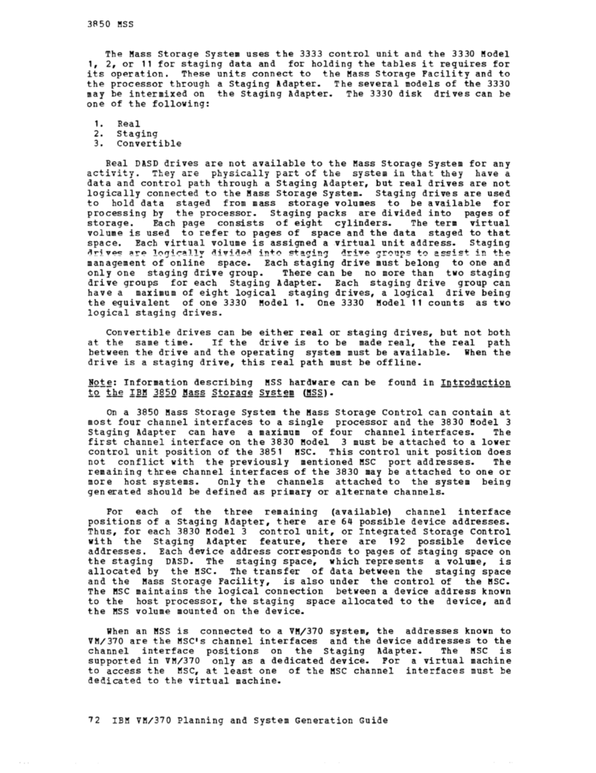
3A 50 MSS The Mass storage System uses the 3333 control unit and the 3330 1, 2, or 11 for staging data and for holding the tables it requires for
its operation. These units connect to the Mass Storage Facility and to
the processor through a Staging Adapter. The several models of the 3330 may be intermixed on the Staging Adapter. The 3330 disk drives can be
one of the following:
1. Real
2. Staging
3. Convertible
Real DASD drives are not available to the Mass Storage System for any
activity. They are physically part of the system in that they have a
data and control path through a Staging Adapter, but real drives are not
logically connected to the Mass Storage System. Staging drives are used
to hold data staged from mass storage volumes to be available for
processing by the processor. Staging packs are divided into pages of
storage. Each page consists of eight cylinders. The term virtual
volume is used to refer to pages of space and the data staged to that
space. Each virtual volume is assigned a virtual unit address. Staging staging drive groups to assist in the management of online space. Each staging drive must belong to one and
only one staging drive group. There can be no more than two staging
drive groups for each Staging Adapter. Each staging drive group can
have a maximum of eight logical $taging drives, a logical drive being
the equivalent of one 3330 Model 1. One 3330 Model 11 counts as two
logical staging drives.
Convertible drives can be either real or staging drives, but not both
at the same time. If the drive is to be made real, the real path
between the drive and the operating system must be available. When the
drive is a staging drive, this real path must be offline. Information describing MSS hardware can be found in iQ. ihe IBM .J§50 On a 3850 Mass Storage System the Mass Storage Control can contain at
most four channel interfaces to a single processor and the 3830 Model 3
Staging Adapter can have a maximum of four channel interfaces. The
first channel interface on the 3830 Model 3 must be attached to a lower
control unit position of the 3851 MSC. This control unit position does
not conflict with the previously mentioned MSC port addresses. The
remaining three channel interfaces of the 3830 may be attached to one or
more host systems. Only the channels attached to the system being
generated should be defined as primary or alternate channels.
For each of the three rema1n1ng (available) channel interface pOSitions of a Staging Adapter, there are 64 possible device addresses.
Thus, for each 3830 Model 3 control unit, or Integrated Storage Control
with the Staging Adapter feature, there are 192 possible device
addresses. Each device address corresponds to pages of staging space on
the staging DASD. The staging space, which represents a volume, is
allocated by the MSC. The transfer of data between the staging space
and the Mass storage Facility, is also under the control of the MSC. The MSC maintains the logical connection between a device address known
to the host processor, the staging space allocated to the device, and
the MSS volume mounted on the device. When an MSS is connected to a VM/370 system, the addresses known to VM/370 are the MSCts channel interfaces and the device addresses to the
channel interface pOSitions on the Staging Adapter. The is
supported in VM/370 only as a dedicated device. For a virtual machine
to access the MSC, at least one of the MSC channel interfaces must be
dedicated to the virtual machine.
72 IBM VM/370 Planning and System Generation Guide
Previous Page Next Page