sitions of the initial address. As a consequence, the list
contains 256 eight-bit function bytes. In cases where
it is known that not all eight-bit argument values will
occur, it may be possible to reduce the size of the list.
In a storage-to-storage operation, the operand fields
may be defined in such a way that they overlap. The
effect of this overlap depends upon the operation.
When the operands remain unchanged, as inCOMPARE or TRANSLATE AND TEST, overlapping does not affect
the execution of the operation. In the case ofMOVE, EDIT, and TRANSLATE, one operand is replaced by new
data, and the execution of the operation may be af
fected by the amount of overlap and the manner in
which data are fetched or stored. For purposes of
evaluating the effect of overlapped operands, consider
that data are handled one eight-bit byte at a time. All
overlapping fields are considered valid but, in editing,
overlapping fields give unpredictable results.
Condition Code
The results of most logical operations are used to set
the condition code in the psw. TheLOAD ADDRESS, IN SERT CHARACTERS, STORE CHARACTER, TRANSLATE, and
the moving and shift operations leave this code un
changed. The condition code can be used for decision
making by subsequent branch-on-condition instruc
tions.
The condition code can be set to reHect five types
of results for logical operations: ForCOMPARE LOGICAL the states 0, 1, or 2 indicate that the first operand is
equal, low, or high.
For the logical-connectives, the states° or 1 indi
cate a zero or nonzero result field.
ForTEST UNDER MASK, the states 0, 1, or 3 indicate
that the selected bits are all-zero, mixed zero and one,
or all-one,
ForTRANSLATE AND TEST, the states 0, 1, or 2 indi
cate an all-zero function byte, a nonzero function byte
with the operand incompletely tested, or a last func
tion byte nonzero.
For editing the states0, 1, or 2 indicate a zero, less
than zero, or greater than zero content of the last re
sult field.CONDITION CODE SETTING FOR LOGICAL OPEHA TIONS 0 1 2 3
And zero not zero
Compare Logical equal low high
Edit zero < zero > zero
Edit and Mark zero < zero > zero
Exclusive Or zero not zeroOr zero not zero
Test Under Mask zero mixed one
Translate and Test zero incomplete complete
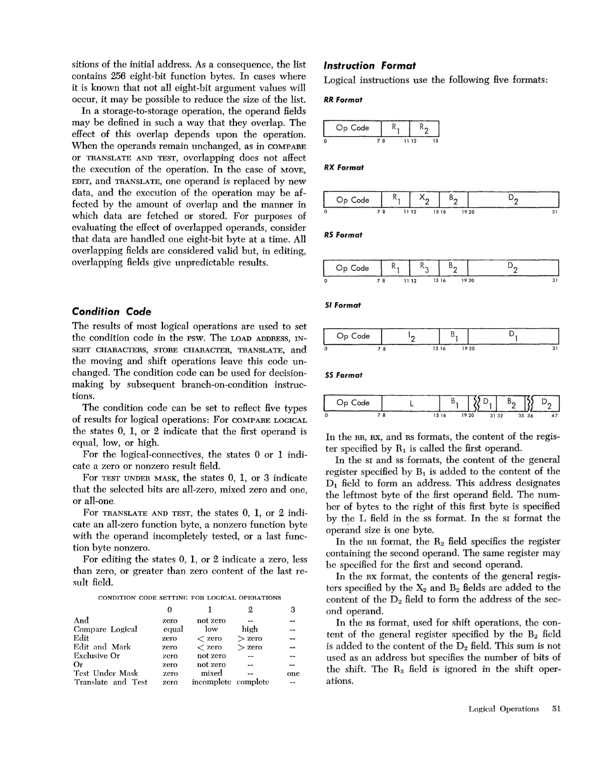
Instruction format
Logical instructions use the following five formats:
RR FormatI Op Code R1 R2
o 78 1112 15
RX FormatOp Code R1
X
2
B2
7 8 11 12 15161920 31
R5 FormatOp Code R1 R3 B2
7 8 11 12 15161920 31
51 FormatOp Code
7 8 15 161920 31 5S Format Op Code L
B1I IJ3J 78 1516 1 9 20 31 32 35 36 47
In the RR, RX, andRS formats, the content of the regis
ter specified by Rl is called the first operand.
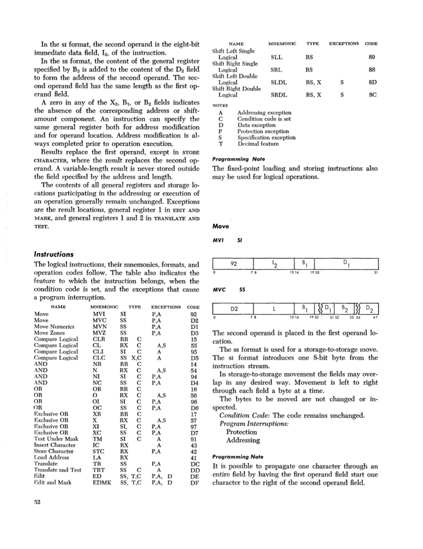
In theSI and ss formats, the content of the general
register specified by Bl is added to the content of the
Dl field to form an address. This address deSignates
the leftmost byte of the first operand field. The num
ber of bytes to the right of this first byte is specified
by the L field in the ss format. In theSI format the
In the RR format, theR2 field specifies the register
containing the second operand. The same register may
be specified for the first and second operand.
In the RX format, the contents of the general regis
ters specified by the X2 and B2 fields arc added to the
content of the D2 field to form the address of the sec
ond operand.
In theRS format, used for shift operations, the con
tent of the general register specified by the B2 field
is added to the content of the D2 field. This sum is not
used as an address but specifies the number of bits of
the shift. TheRH field is ignored in the shift oper
ations.
Logical Operations 51
contains 256 eight-bit function bytes. In cases where
it is known that not all eight-bit argument values will
occur, it may be possible to reduce the size of the list.
In a storage-to-storage operation, the operand fields
may be defined in such a way that they overlap. The
effect of this overlap depends upon the operation.
When the operands remain unchanged, as in
the execution of the operation. In the case of
data, and the execution of the operation may be af
fected by the amount of overlap and the manner in
which data are fetched or stored. For purposes of
evaluating the effect of overlapped operands, consider
that data are handled one eight-bit byte at a time. All
overlapping fields are considered valid but, in editing,
overlapping fields give unpredictable results.
Condition Code
The results of most logical operations are used to set
the condition code in the psw. The
the moving and shift operations leave this code un
changed. The condition code can be used for decision
making by subsequent branch-on-condition instruc
tions.
The condition code can be set to reHect five types
of results for logical operations: For
equal, low, or high.
For the logical-connectives, the states
cate a zero or nonzero result field.
For
that the selected bits are all-zero, mixed zero and one,
or all-one,
For
cate an all-zero function byte, a nonzero function byte
with the operand incompletely tested, or a last func
tion byte nonzero.
For editing the states
than zero, or greater than zero content of the last re
sult field.
And zero not zero
Compare Logical equal low high
Edit zero < zero > zero
Edit and Mark zero < zero > zero
Exclusive Or zero not zero
Test Under Mask zero mixed one
Translate and Test zero incomplete complete
Instruction format
Logical instructions use the following five formats:
RR Format
o 78 1112 15
RX Format
X
2
B2
7 8 11 12 1516
R5 Format
7 8 11 12 1516
51 Format
7 8 15 16
B1
In the RR, RX, and
ter specified by Rl is called the first operand.
In the
register specified by Bl is added to the content of the
Dl field to form an address. This address deSignates
the leftmost byte of the first operand field. The num
ber of bytes to the right of this first byte is specified
by the L field in the ss format. In the
In the RR format, the
containing the second operand. The same register may
be specified for the first and second operand.
In the RX format, the contents of the general regis
ters specified by the X2 and B2 fields arc added to the
content of the D2 field to form the address of the sec
ond operand.
In the
tent of the general register specified by the B2 field
is added to the content of the D2 field. This sum is not
used as an address but specifies the number of bits of
the shift. The
ations.
Logical Operations 51