In the SI format, the second operand is the eight-bit
immediate data field, 12, of the instruction.
In theS8 format, the content of the general register
specified by B2 is added to the content of the D2 field
to form the address of the second operand. The sec
ond operand field has the same length as the first op
erand field.
A zero in any of the X2, B1, or B2 fields indicates
the absence of the corresponding address or shift
amount component. An instruction can specify the
same general register both for address modification
and for operand location. Address modification is al
ways completed prior to operation execution.
Results replace the first operand, except inSTORE CHARACTER, where the result replaces the second op
erand. A variable-length result is never stored outside
the field specified by the address and length.
The contents of all general registers and storage lo
cations participating in the addressing or execution of
an operation generally remain unchanged. Exceptions
are the result locations, general register 1 in EDIT AND
MARK, and general registers 1 and 2 inTRANSLATE AND TEST. Instructions
The logicalinstructions, their mnemonics, formats, and
operation codes follow. The table also indicates the
feature to which the instruction belongs, when the
condition code is set, and the exceptions that cause
a program interruption.NAME MNEMONIC TYPE EXCEPTIONS CODE Move MVI SI P,A 92
MoveMVC SS P,A D2
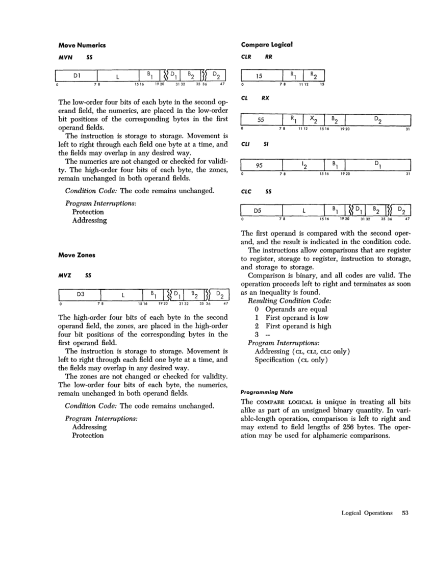
Move NumericsMVN SS P,A Dl
Move ZonesMVZ SS P,A D3 Compare Logical CLR RR C 15 Compare Logical CL RX C A,S 55 Compare Logical CLI SI C A 95 Compare Logical CLC SS X,C A D5
AND NR RR C 14
AND N RX CA,S 54
AND NISI C P,A 94
AND NCSS C P,A D4 OR OR RR C 16 OR 0 RX C A,S 56 OR 01 SI C P,A 96 OR OC SS C P,A D6
ExclusiveOR XR RR C 17
ExclusiveOR X RX C A,S 57
ExclusiveOR XI SI, C P,A 97
ExclusiveOR XC SS C P,A D7
TestUnder Mask TM SI C A 91
Insert Character IC RX A 43Store Character STC RX P,A 42
Load Address LA RX 41
Translate TRSS P,A DC
Translate and Test TRTSS C A DD
Edit EDSS, T,C P,A, D DE F:dit and Mark EDMK SS, T,C P,A, D DF ,52 NAME MNEMONIC TYPE EXCEPTIONS CODE Shift Left Single Logical SLL RS 89 Shift Right Single Logical SRL RS 88 Shift Left Double
LogicalSLDL RS, X S 8D Shift Right Double
LogicalSRDL RS, X S 8C NOTES A Addressing exception
C Condition code is set
D Data exceptionP Protection exception S Specification exception
T Decimal feature
Programming Note
The fixed-point loading and storing instructions also
may be used for logical operations.
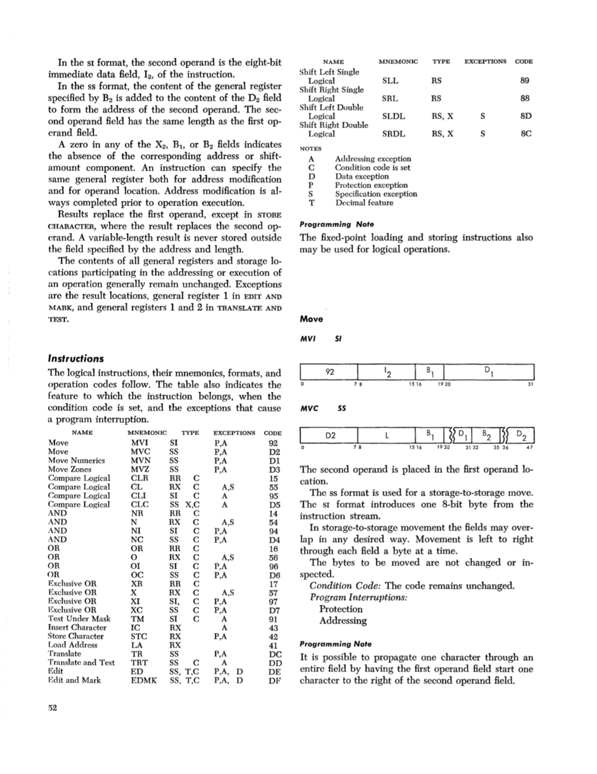
Move
MVI 51
92
7 8 1516 1920 31
MVC 55
D2
7 8 1516
The second operand is placed in the first operand lo
cation.
The ss format is used for a storage-to-storage move.
TheSI format introduces one 8-bit byte from the
instruction stream.
In storage-to-storage movement the fields may over
lap in any desired way. Movement is left to right
through each field a byte at a time.
The bytes to be moved are not changed or in
spected.
Condition Code: The code remains unchanged.Program Interruptions:
Protection
Addressing
Programming Note
It is possible to propagate one character through an
entire field by having the first operand field start one
character to the right of the second operand field.
immediate data field, 12, of the instruction.
In the
specified by B2 is added to the content of the D2 field
to form the address of the second operand. The sec
ond operand field has the same length as the first op
erand field.
A zero in any of the X2, B1, or B2 fields indicates
the absence of the corresponding address or shift
amount component. An instruction can specify the
same general register both for address modification
and for operand location. Address modification is al
ways completed prior to operation execution.
Results replace the first operand, except in
erand. A variable-length result is never stored outside
the field specified by the address and length.
The contents of all general registers and storage lo
cations participating in the addressing or execution of
an operation generally remain unchanged. Exceptions
are the result locations, general register 1 in EDIT AND
MARK, and general registers 1 and 2 in
The logicalinstructions, their mnemonics, formats, and
operation codes follow. The table also indicates the
feature to which the instruction belongs, when the
condition code is set, and the exceptions that cause
a program interruption.
Move
Move Numerics
Move Zones
AND NR RR C 14
AND N RX C
AND NI
AND NC
Exclusive
Exclusive
Exclusive
Exclusive
Test
Insert Character IC RX A 43
Load Address LA RX 41
Translate TR
Translate and Test TRT
Edit ED
Logical
Logical
C Condition code is set
D Data exception
T Decimal feature
Programming Note
The fixed-point loading and storing instructions also
may be used for logical operations.
Move
MVI 51
92
7 8 1516 1920 31
MVC 55
D2
7 8 1516
The second operand is placed in the first operand lo
cation.
The ss format is used for a storage-to-storage move.
The
instruction stream.
In storage-to-storage movement the fields may over
lap in any desired way. Movement is left to right
through each field a byte at a time.
The bytes to be moved are not changed or in
spected.
Condition Code: The code remains unchanged.
Protection
Addressing
Programming Note
It is possible to propagate one character through an
entire field by having the first operand field start one
character to the right of the second operand field.