four bits are inspected for a sign code immediately
after the leftmost four bits are examined.
Any of the plus-sign codes1010, 1100, 1110, or 1111
will set theS trigger to zero after the digit is in
spected, whereas the minus-sign codes1011 and 1101 will leave the S trigger unchanged. When one of these
sign codes is encountered in the four rightmost bits,
these bits no longer are treated as a digit, and a new
character is fetched from storage for the next digit to
be examined.
A plus sign sets theS trigger to zero even if the trig
ger was set to one for a nonzero digit in the same
source byte or by a significance-start character for that
digit.
Fill Character: Thefill character is obtained from
the pattern as part of the editing operation. Thefirst character of the pattern is used as a fill character and
is left unchanged in the result field, except when it is
the digit-.select or significance-start character. In the
latter cases a digit is examined and, when nonzero,
inserted.
Result Condition: To facilitate the blanking of all
zero fields, the condition code is used to indicate the
sign and zero status of the lastfield edited. All Jigits
examined are tested for the code0000. The presence
or absence of an all-zero sourcefield is recorded in the
condition code at the termination of the editing oper
ation.
1. The condition code is made0 for a zero source
field, regardless of the state of theS trigger.
2. For a nonzero sourcefield and an S trigger of
one, the code is made 1 to indicate less than zero.
3. For a nonzero sourcefield and an S trigger of
zero, the code is made 2 to indicate greater than zero.
The condition-code setting pertains to fields as spe
cified by the field-separator characters, regardless of
the number of signs encountered.
For the multiple-field editing operations the con
dition-code setting reflects only the field following the
last field-separator character. When the last character
of the pattern is a field-separator character, the con
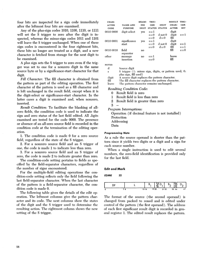
dition code is madeO. The following table gives the details of the edit op
eration. The leftmost columns give the pattern char
acter and its code. The next columnssnow the states
of the digit and theS trigger used to determine thc
resulting action. The rightmost column shows the new
setting of theS trigger.
58
CHAR- EXAM- TRIG-RESULT TRIG-
ACTER NAME AND INE GER DIGIT CHAR-GERCODE PURPOSE DIGIT STATUS STATUS ACTER SET 0010 0000 digit select yes s=l digit s=O dnotO digit s=l s=O d=O fill 00100001 significance yes s=l digit
starts=O d nota digit s=l s=O d=O fill s=l 00100010 field no fill s=O separator
other message no s=l leave
insertions=O fill NOTES d Source digit
S trigger (1: minus sign, digits, or pattern used;0: plus sign, fill used) digit A source digit replaces the pattern character.
fill The fill character replaces the pattern character.
leave The pattern character remains unchanged.
Resulting Condition Code:
o Resultfield is zero
1 Result field is less than zero
2 Result field is greater than zero
3Program Interruptions: Operation (if decimal feature is not installed)
Protection
Addressing
Data
Programming Note
As a rule the source operand is shorter than the pat
tern since it yields two digits or a digit and a sign for
each source number.
When a single instruction is used to edit several
numbers, the zero-field identification is provided only
for the last field.
Edit and Mark
EDMK55 DF L
B1I
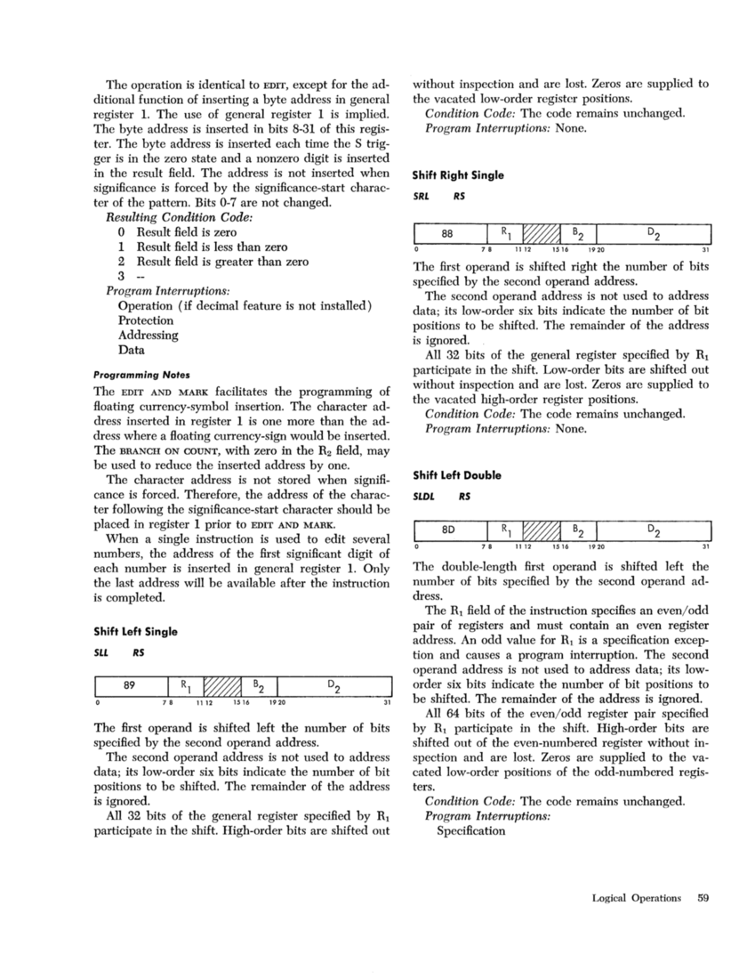
The format of the source (the second operand) is
changed from packed to zoned and is edited under
control of the pattern (the first operand). The address
of each first significant result digit is recorded in gen
eral register 1. The edited result replaces the pattern.
after the leftmost four bits are examined.
Any of the plus-sign codes
will set the
spected, whereas the minus-sign codes
sign codes is encountered in the four rightmost bits,
these bits no longer are treated as a digit, and a new
character is fetched from storage for the next digit to
be examined.
A plus sign sets the
ger was set to one for a nonzero digit in the same
source byte or by a significance-start character for that
digit.
Fill Character: The
the pattern as part of the editing operation. The
is left unchanged in the result field, except when it is
the digit-.select or significance-start character. In the
latter cases a digit is examined and, when nonzero,
inserted.
Result Condition: To facilitate the blanking of all
zero fields, the condition code is used to indicate the
sign and zero status of the last
examined are tested for the code
or absence of an all-zero source
condition code at the termination of the editing oper
ation.
1. The condition code is made
field, regardless of the state of the
2. For a nonzero source
one, the code is made 1 to indicate less than zero.
3. For a nonzero source
zero, the code is made 2 to indicate greater than zero.
The condition-code setting pertains to fields as spe
cified by the field-separator characters, regardless of
the number of signs encountered.
For the multiple-field editing operations the con
dition-code setting reflects only the field following the
last field-separator character. When the last character
of the pattern is a field-separator character, the con
dition code is made
eration. The leftmost columns give the pattern char
acter and its code. The next columns
of the digit and the
resulting action. The rightmost column shows the new
setting of the
58
CHAR- EXAM- TRIG-
ACTER NAME AND INE GER DIGIT CHAR-GER
start
other message no s=l leave
insertion
S trigger (1: minus sign, digits, or pattern used;
fill The fill character replaces the pattern character.
leave The pattern character remains unchanged.
Resulting Condition Code:
o Result
1 Result field is less than zero
2 Result field is greater than zero
3
Protection
Addressing
Data
Programming Note
As a rule the source operand is shorter than the pat
tern since it yields two digits or a digit and a sign for
each source number.
When a single instruction is used to edit several
numbers, the zero-field identification is provided only
for the last field.
Edit and Mark
EDMK
B1
The format of the source (the second operand) is
changed from packed to zoned and is edited under
control of the pattern (the first operand). The address
of each first significant result digit is recorded in gen
eral register 1. The edited result replaces the pattern.