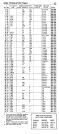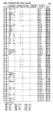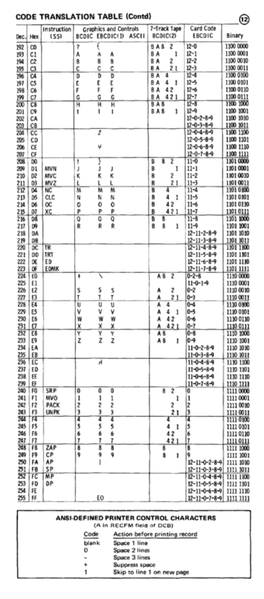
Dec. Hex
197
209
213
215
219 DB
220
223
226 E2
227 E3
228 E4
229 E5
231 E7
232 E8
233 E9
234 EA
235 EB
236
238 EE
239 EF
240
242 F2
243 F3
244 F4
245 F5
246 F6
247 F7
248 F8
249 F9
250 FA
251 FB
252
255 FF
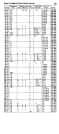
B B B BA 2 12-2
E E E BA 4 1 12-5
F F F BA 42 12-6
G G G B A 421 12-7
H H H BA8 12-8
12-{)-2-8-9
12-{)-3-8-9
12-{)-5-8-9
y 12-{)-6-8-9
12-{)-7-8-9
! } B 8 2 11-0
Q Q Q B 8 11-8
R R R B 8 1 11-9
12-11-2-8-9
12-11-3-8-9
TR 12-ll-4-8-9
TRT 12-lI-5-8-9
ED 12-11-6-8-9
EDMK 12-11-7-8-9
4 4 4 4 4
5 5 5 4 I 5
6 6 6 42 6
7 7 7 421 7
ZAP 8 8 8 8 8
(A in
blank
1
Binary
III I