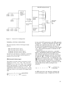
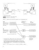
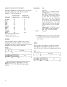
The following introduction to start/stop (asynchro
nous) type operations uses as examples IBM typeterminals, such as the 1030, 1050, 1060, and 2740. The transmission of data by means of start/stop
type communications involves, for example, the
coding of each character with a start bit and a stop
bit, in addition to the data bits and possibly a check
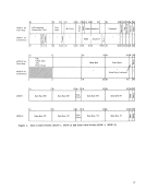
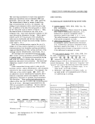
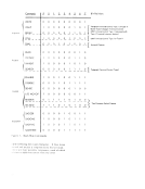
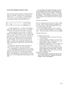
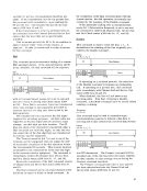
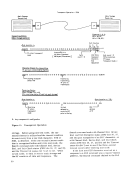
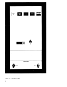
bit for odd parity such as shown in Figure 5. Thus,
the transmission of characters can occur at an
irregular rate, since each character contains its own
sync information (character timing). This is parti
cularly useful for transmission from unbuffered
units such as keyboards and devices requiring the
manual insertion of input documents (badge readers,
card readers, etc.).Start/ stop communications require the use of a
unique set of line-control characters to provide for
communications-line discipline (polling and addres
sing) and identification of the various portions of the
message (station identification, text blocks, etc.).
All messages are transmitted during text mode,
after certain control operations are first performed
in control mode. All characters transmitted during
text mode are either printable data characters or
functional characters (not printable). The functional
characters consist of such codes asCR/LF, delete,
and idle.Codes transmitted during control mode provide
terminal control, station identification, and component
selection for the remote terminal. For example, the1050 uses a line-control signal, © --EOT, and
an alphabetic station-identification character and a
numeric component-select code (together with the
appropriate response) to maintain communications
line discipline. These polling and addressing pro
cedures allow the2703 to control the communications
line at all times. Messages transmitted from the2703 are preceded by an address. Remote stations
have the opportunity to transmit only when polled
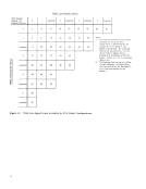
from the2703. *8 Indicates no 8-bit
Figure 5. Bit Configuration of a"G" Character
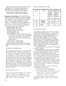
(Serialized)START/STOP COMMUNICATIONS CAPABILITIES LINE CONTROL The following are transmitted during control mode: • Control signals--EOT, EOA, EOB, Yes, No, SOA, and Inquiry. • Polling characters--These consist of an alpha
betic station -identification character, A -Z ,
followed by a numeric component-select
character (used by the1050), 5, 6, 7, or o.
The polled terminal is requested to transmit,
if the polled component is ready.• Addressing characters--These also consist of
an alphabetic station-identification character,A-Z, followed by a numeric component-select
character (used by the1050), 1,2,3,4, or9.
The addressed terminal is requested to receive,
if the addressed component is ready.
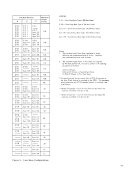
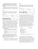
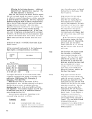
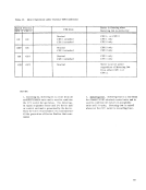
The line-controlsignals--EOT, EOA, EOB, Yes,
No,SOA, and Inquiry--are represented in a short
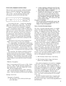
hand form--© 'CD , @ , (i) , ® , ® ' and @ , respectively (Figure 6). is used in
programming as well as in communications and line
control discussions. Also, the terms"response" and "answer" are used in the following restricted manner:
1. Answcr--The negative or positive reply, or no
rep.1y at all, to anLRC compare.
2. Response--The negative or positive reply, or
no reply at all, to a component-select charac
ter (addressing or polling).
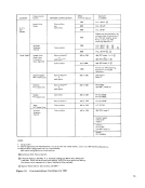
Description SymbolProcessor Bi t Processor Configuration Character End of Transaction (EaT)
©C-8-4-2-1 r(TapeMark) End of Address (EOA) @ 8-2-1
#(Pound Sign)
End of Block(EOB) ® C-A-8-4-2 't (Record IV Jrk) Positive Response (YES) G) B-A-8-2-1 (Period) Negative ResponsE' (NO) @ B -(Hyphen)
Address Select(SOA) CD C-A-8-2-1 , (Comma) Positive Response (Inquiry) 0 8-2-1 it (Pound Sign)
Figure 6. Line-Control Characters
23
nous) type operations uses as examples IBM type
type communications involves, for example, the
coding of each character with a start bit and a stop
bit, in addition to the data bits and possibly a check
bit for odd parity such as shown in Figure 5. Thus,
the transmission of characters can occur at an
irregular rate, since each character contains its own
sync information (character timing). This is parti
cularly useful for transmission from unbuffered
units such as keyboards and devices requiring the
manual insertion of input documents (badge readers,
card readers, etc.).
unique set of line-control characters to provide for
communications-line discipline (polling and addres
sing) and identification of the various portions of the
message (station identification, text blocks, etc.).
All messages are transmitted during text mode,
after certain control operations are first performed
in control mode. All characters transmitted during
text mode are either printable data characters or
functional characters (not printable). The functional
characters consist of such codes as
and idle.
terminal control, station identification, and component
selection for the remote terminal. For example, the
an alphabetic station-identification character and a
numeric component-select code (together with the
appropriate response) to maintain communications
line discipline. These polling and addressing pro
cedures allow the
line at all times. Messages transmitted from the
have the opportunity to transmit only when polled
from the
Figure 5. Bit Configuration of a
(Serialized)
betic station -identification character, A -
followed by a numeric component-select
character (used by the
The polled terminal is requested to transmit,
if the polled component is ready.
an alphabetic station-identification character,
character (used by the
The addressed terminal is requested to receive,
if the addressed component is ready.
The line-control
No,
hand form--© '
programming as well as in communications and line
control discussions. Also, the terms
1. Answcr--The negative or positive reply, or no
rep.1y at all, to an
2. Response--The negative or positive reply, or
no reply at all, to a component-select charac
ter (addressing or polling).
Description Symbol
©
#
End of Block
Address Select
Figure 6. Line-Control Characters
23