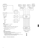
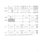
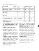
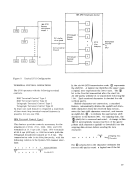
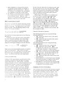
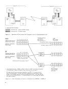
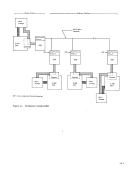
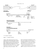
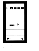
-------Station A ----------..., ",,-------- Station B ------- ....... , Main
StorageS/360 CPU X = Appl i cable Data Set/Modem
Synchronous
Feature X2703 '00W& Information Path - Control Unit/Main Storage 8888888&§ Information Path - CPU/Main Storage
X
Sync hronous
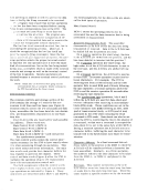
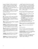
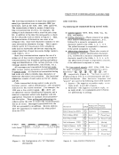
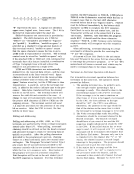
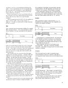
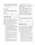
Feature2703 Figure 11. Operation of Two System/360 Computers over a Communications Line EBCDIC Translate Operation
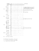
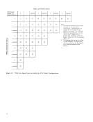
via TranslateE" E] t2 E3 E4 E5 E6 E7 (TR) Instruction Character Received from
v
Communication Facility0 0 Bit positions in byte _
Character Transferred to0 0 Main Storage Bit nome In byte- SBT 0 2 3 4 5
Character Received fromEBCDIC Communi cation Faci lity !::. !::. 0 0 Translate
Tables
Character Transferred to0 0 0 0 Main Storage Positions Filled
Bit Structure for thisexample is letter P !J. Unused data bit positions. EBCDIC, USASCII, ASCII-8, and SBT code charts are presented
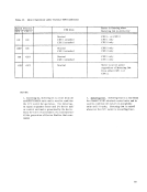
in the pubiication"Generai information, Binary Synchronous Comrnunicotion". All codes from the line are received and assembled in the 2703. If the code structure is
fewer than eight data bits, it is right justified and transferred to its bytelocation in main
storage. Any missing bit positions in the main storage byte arefilled. If the code received
from the iine has an 8-bit structure, it is transferreddirectly to its main storage byte location as in above examples. Figure 12. Code Translation of a Received Character (to EBCDIC or ASCII-8)
52
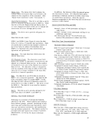
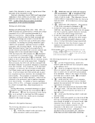
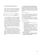
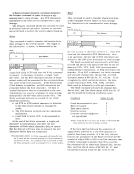
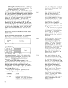
Main
StorageChannel :
___-.J S/360 Main Storage 0 2 3 4 0 2 3 4 G 2 3 4 0 2 3 4 0 2 3 4 5/360 CPU 5 6
5 6
5 6
5 6
5 6
7 6 X 5 4 3 2..... - ., After trans I ation,
7 and X contain
samevalue. 7
7
7
7
7
Storage
Synchronous
Feature X
X
Sync hronous
Feature
via Translate
v
Communication Facility
Character Transferred to
Character Received from
Tables
Character Transferred to
Bit Structure for this
in the pubiication
fewer than eight data bits, it is right justified and transferred to its byte
storage. Any missing bit positions in the main storage byte are
from the iine has an 8-bit structure, it is transferred
52
Main
Storage
___
5 6
5 6
5 6
5 6
7 6 X 5 4 3 2
7 and X contain
same
7
7
7
7