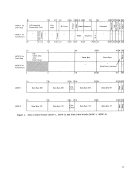
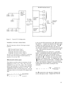
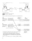
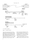
A specific line base is assigned as the first line
base within the continuous span of addresses. Then
a line set of eight line adapters is added for this line
base. As many lines as desired (up to eightlineE for start/ stop, or four lines for synchronous opera
tion) are attached to this line set. Addresses are
assigned to all eight lines even if lines are not attached.¥lhen the first line base is filled--or has as many lines
attached as desired--the addresses are assigned to the
second line base in the same manner. Similarly, ad
dresses are assigned to the third line base if it is
attached to the 2703.
If two2703's are placed on the channel, the
second 2703 may be placedwith its lowest address
in the next increment of 16 not assigned to the first
2703. Address assignment has no bearing on the
priority ofany particular line. This is a function of
the type of line base only.
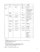
Address-Assignment Considerations
Numerous things should be considered when deter
mining the 2703 address assignments. However,
all these various items can be associated with the
following list of major considerations involving
address assignment:
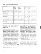
1. A multiplexer channel can accommodate a
maximum of 256 individual addresses.NOTE: Each address is associated with an individual sub channel
withinthe multiplexer channel. ThE: c:apabilitics of a specific channel are
dictated by the IBM System/360 processor
model employed and the available core storage.
Refer to"Maximum Lines Available by
Processor Model." 2. The specific address range available for
assignment is0 to 255.
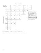
3. Any one 2703 is limited to a maximum of 176
individual addresses (or lines).
4. The low-address boundary for address assign
ment should be either0 or a 16-unit increment
thereof (for examp!e--1&, 32, or 48).NOTE: A boundary of 48 should be used if convenient. This start ing number reserves sufficient positions to allow the channel ;,tt:ichmcnt of other devices with standard assigned addresses (for example, the standard assigned address for the 1050 Docu
mentary Console is 31 or'1F'*). This also simplifies installa
tion, since the low-boundary address of 48 is prewired before
shipping.
5. The high-address boundary must be an even
increment of either 8 (for startl stop) or 4
(for synchronous) from the low-address
boundary within the 2703.
6. The10\\lest address within the 2703 is always
assigned as the wrap address. The wrapi< , , is Hexadecimal representation.
address is the address of the line used to read
data back to the channel from any line issued
the Wrap command. The wrap address and its
associated line can be used for normal trans
mission at all times, except when the 2703
is being checked with a Wrap command. Refer
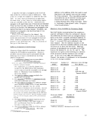
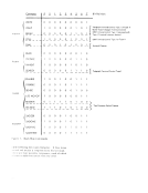
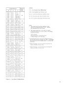
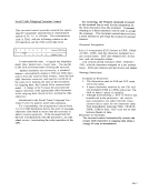
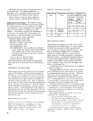
to"Automatic Wrap-around" under "Program ming Considerations. " Maximum Lines Available by Processor Model
Each half-duplex communications line requires a
separate subchannel within the multiplexer channel.
The addresses for these lines are assigned sequen
tially on the 2703, normally starting at address 16.
(See item 4 under "Address-Assignment Considera
tions.") A second 2703 can be attached to the
same channel. The low -address bounda.ry of the
second 2703 is the first available address in the next
increment of 16 above the first 2703. Different
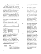
numbers of subchannels are available on the IBM
System/360 Models30, 40, 50, 65, and 75. The
maximums are given in the following as a function
of the processor and the minimum core-storage
size. In the case of the mM 2780 Multiplexer
Channel, the number of subchannels is not dependent
on the core storage available.
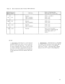
Processor Number of Minimum Core-StoragE
Model Sub channels
Model C30 Model D 30 Model ElF 30 Model D 40 Model E 40 Model F 40 Model G/H 40 Model F 50 Model G 50 Model HII 50 Processor Model
with 2870
Model 65
Model 75
32
96
224
16
32
64
128
64
128
256
Number of
Subchannels
192
192
Size (Bytes)
8K
16K
32K-64K and
Feature#5250* 16K
32K
64K
128K
64K
128K
256K-512K and
Feature#5250* *Additional Multiplexer SubchalUlels special feature
13
base within the continuous span of addresses. Then
a line set of eight line adapters is added for this line
base. As many lines as desired (up to eight
tion) are attached to this line set. Addresses are
assigned to all eight lines even if lines are not attached.
attached as desired--the addresses are assigned to the
second line base in the same manner. Similarly, ad
dresses are assigned to the third line base if it is
attached to the 2703.
If two
second 2703 may be placed
in the next increment of 16 not assigned to the first
2703. Address assignment has no bearing on the
priority of
the type of line base only.
Address-Assignment Considerations
Numerous things should be considered when deter
mining the 2703 address assignments. However,
all these various items can be associated with the
following list of major considerations involving
address assignment:
1. A multiplexer channel can accommodate a
maximum of 256 individual addresses.
within
dictated by the IBM System/360 processor
model employed and the available core storage.
Refer to
Processor Model.
assignment is
3. Any one 2703 is limited to a maximum of 176
individual addresses (or lines).
4. The low-address boundary for address assign
ment should be either
thereof (for examp!e--1&, 32, or 48).
mentary Console is 31 or'1F'*). This also simplifies installa
tion, since the low-boundary address of 48 is prewired before
shipping.
5. The high-address boundary must be an even
increment of either 8 (for startl stop) or 4
(for synchronous) from the low-address
boundary within the 2703.
6. The
assigned as the wrap address. The wrap
address is the address of the line used to read
data back to the channel from any line issued
the Wrap command. The wrap address and its
associated line can be used for normal trans
mission at all times, except when the 2703
is being checked with a Wrap command. Refer
to
Each half-duplex communications line requires a
separate subchannel within the multiplexer channel.
The addresses for these lines are assigned sequen
tially on the 2703, normally starting at address 16.
(See item 4 under "Address-Assignment Considera
tions.
same channel. The low -address bounda.ry of the
second 2703 is the first available address in the next
increment of 16 above the first 2703. Different
numbers of subchannels are available on the IBM
System/360 Models
maximums are given in the following as a function
of the processor and the minimum core-storage
size. In the case of the mM 2780 Multiplexer
Channel, the number of subchannels is not dependent
on the core storage available.
Processor Number of Minimum Core-StoragE
Model Sub channels
Model C
with 2870
Model 65
Model 75
32
96
224
16
32
64
128
64
128
256
Number of
Subchannels
192
192
Size (Bytes)
8K
16K
32K-64K and
Feature
32K
64K
128K
64K
128K
256K-512K and
Feature
13