for attachment to channel "one" may be different
from the address group(s) valid for attachment to
channel"two. " Only the attached channel can cause the TPS to
automatically return to the neutral state.\Vhen the
switch to the neutral state occurs, the entire2703 is
involved (all lines). This return to neutral may be
accomplished by one of two automatic methods:
1. If a system reset is signaled by the attached
channel, theTPS unconditionally returns to the
neutr al state.
2. If a Release command is issued by the attached
channel to any of the valid2703 addresses for
that channel and the command is honored, theTPS returns to the neutral state. To honor the
Release command, the2703 must be "command free" (no line executing a command). If it is not
command-free, it will respond to initial selec
tion by setting Channel End, Device End, andUnit Exception and will not go to the neutral
state (seeNote 2).
Two manual methods whereby the operator may
switch to the neutral statethrough manual interven
tion are:
22
1. A power-on reset, initiated by pressing the
Power-On pushbutton, causes theTPS to uncon
ditionally return to the neutral state.
2. If the Meter switchon the operator's panel is
switched to theOFF position, the TPS causes
the2703 to go off-line only when the attached CPU is in a halt or wait state and the 2703 is
command free. After going off-line, theTPS re
turns to the neutral state. If theTPS is in a neu
tral state, the2703 will become unavailable when
bothCPU-l and CPU-2 come to a wait state and
the meter switch is in theOFF position. While
the Meter switch is in theOFF position, the TPS cannot be set to an attached state with either
channel. When the Meter switch isON. the 2703 will go on-line when both CPU-l and CPU-2 are
in a halt or wait state,
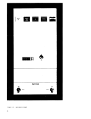
TheTPS feature is activated by two manually
operated partition switches on the operator's panel(CPU-lON/OFF and CPU-2 ON/OFF). These
switches permit the operator to initiate a partition
(cutoff) of either processor. These switches can
be operated for partitioning at any time, but are
effective only when:
1. The2703 is in neutral state,
2. TheCPU reaches a halt or wait state, with the
partition switch for theCPU to be partitioned (CPU-lor CPU-2) set to OFF. NOTES: 1. If both CPU-l and CPU-2 are partitioned, the 2703 is
effectively off-line relative to system availability.
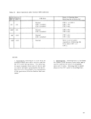
2. The2703 requires a variable length of time from the
sending of the ending status condition to the channel, until
detection of the command free state is accomplished. The
maximum time period required for detection of the command
free state is influenced by the type of Start/ Stop base installed
in the2703, as follows:
Start/ Stop Base Type 1--11 ms. max.
Start/ Stop Base Type II--4 ms. max.
If the Release command is presented to the2703 too soon
following the execution of the last command, the Release
command will not be honored, since the2703 will appear to
the program as not being command free. In addition,
Release should be issued under a unique StartI/O instruction
with no command chaining.
from the address group(s) valid for attachment to
channel
automatically return to the neutral state.
switch to the neutral state occurs, the entire
involved (all lines). This return to neutral may be
accomplished by one of two automatic methods:
1. If a system reset is signaled by the attached
channel, the
neutr al state.
2. If a Release command is issued by the attached
channel to any of the valid
that channel and the command is honored, the
Release command, the
command-free, it will respond to initial selec
tion by setting Channel End, Device End, and
state (see
Two manual methods whereby the operator may
switch to the neutral state
tion are:
22
1. A power-on reset, initiated by pressing the
Power-On pushbutton, causes the
ditionally return to the neutral state.
2. If the Meter switch
switched to the
the
command free. After going off-line, the
turns to the neutral state. If the
tral state, the
both
the meter switch is in the
the Meter switch is in the
channel. When the Meter switch is
in a halt or wait state,
The
operated partition switches on the operator's panel
switches permit the operator to initiate a partition
(cutoff) of either processor. These switches can
be operated for partitioning at any time, but are
effective only when:
1. The
2. The
partition switch for the
effectively off-line relative to system availability.
2. The
sending of the ending status condition to the channel, until
detection of the command free state is accomplished. The
maximum time period required for detection of the command
free state is influenced by the type of Start/ Stop base installed
in the
Start/ Stop Base Type 1--11 ms. max.
Start/ Stop Base Type II--4 ms. max.
If the Release command is presented to the
following the execution of the last command, the Release
command will not be honored, since the
the program as not being command free. In addition,
Release should be issued under a unique Start
with no command chaining.