M
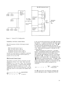
_xponder feature
expander
expander
4
expander
14
??
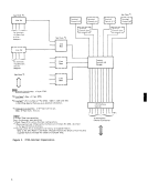
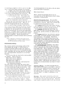
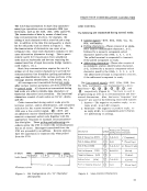
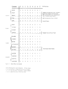
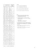
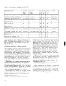
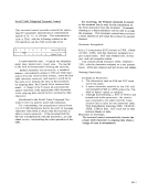
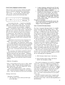
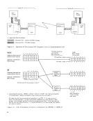
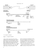
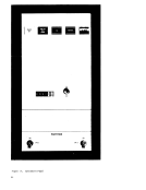
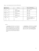
Model 1 ana Expander Feature
1 expander 2 expander 3 expander
8
22 24 32 34 42 44
44 46
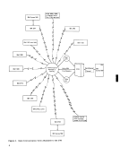
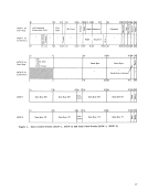
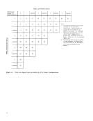
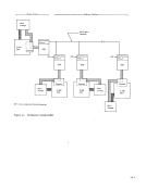
Figure
38
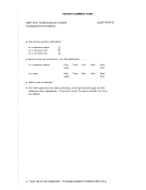
l. The total
peed line terminations
ny given 2712
configuration is determined by the
the Modell and
nates. A" i ndi cated
cumulative, thus the
intersection of
Model 2 coordi
features are ac
second model 1 adapter feature
assumes prior attachment of the first
model
feature, etc.
2. The Expander features require a block
of eight addresses, while providing
two line terminations for the Model
Model 2.