character is always acted upon; it is also included in
the bcc accumulation.
Each time an ITB is detected, theSF checks the
bcc accumulation and passes on to main storage an
Error Index byte following the ITB (or ETB or ETX)
character provided theSF is in error index byte
mode. If the Error Index byte mode is not set, the
Error Index byte will not be passed on to main stor
age. The Error Index byte (EIB) reflects the condi
tion of the last block of data recei ved (a non-zero
content indicates a transmission error).
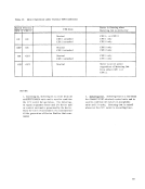
The EIB informs the program of data-check or
overrun conditions detected while the block of datawati ut;;ing rt;;ceived. These conditions set the
following bits in the Em:
Bit Position
4
5
Condition
Data Check
Overrun
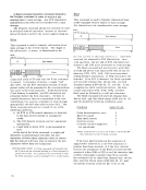
The Em character is stored in the byte location
immediately following the ITB (or ETB or ETX)
character of the data block involved in the read
operation.
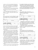
The ITB character is used to break up a long
record into shorter blocks; each block (except the
last) is ended with an ITB character. The direction
of transmission is not reversed following the ITB,
as it is following the ETX.
The record will end normally upon detection of
an ETB or ETX character. When theSF is not in
text or transparent mode, DLE-Stick (followed by a
valid pad character) will end a read-type command
with Channel End and Device End status.Some of
the defined DLE-Stick sequences are: ACK0, ACK 1, WACK, and RVI. The DLE-Stick sequence
will be treated like the NAK character.
Both characters must be of proper parity when
parity checking is performed. All DLE sequences
must be contiguous characters. If text mode is set,
the DLE-Control sequence will be treated as data
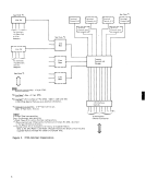
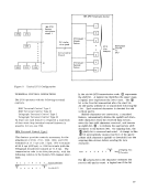
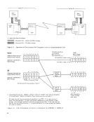
and included in the bcc accumuladon.SYNCHRONOUS OPERATIONS The Synchronous Base (SB) provides the circuitry
for two-way, nonsimultaneous (half-duplex), serial,
synchronous data communication overbased or
switched transmission facilities having voice-grade
qualities. Information transmission (consisting
of data bytes, logical information, line-control
characters, error-checking characters, etc.)
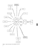
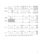
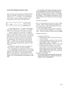
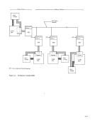
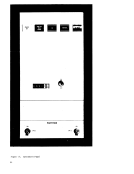
consists of binary streams, serial by bit and by50 character, between two BSC-adapted stations. The
stations operating over the data link may beBSC adapted computers, terminal, remote I/O devices,
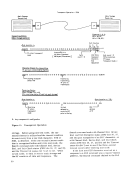
control units, or other equipment. For example,
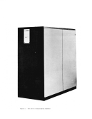
twoSystem/360 computers can typically operate
over a communications path as shown in Figure 11.
The Synchronous Attachment is a prerequisite to
attaching anyESC capability to the 2703. Two
Synchronous Bases can be installed in a2703. The
attachment of the Synchronous Attachment feature
in a2703 requires the installation of the Base
Expansion feature.
Operationally, theSF is fully controlled by the
channel program in conjunction with the data-link
control::;ignals it receives from the remote station
via the communications network and the signals it
receives via the multiplexer channel attached to the
main-storageCPU. The SF performs the following functions: • Provides the required buffering between the 2703 and the attached BSC-adapted remote
station.• Checks the
the2703 and the remote station. • Scans the received data -link-control characters
and control-character sequences and initiates
certain actions.• Initiates data transfer to main storage on read
type commands and to the remote station on
write-type commands.• Automatically generates time-fill and check
characters as r.equired.• Generates several timeouts--of fixed duration-
to prevent system"hang-up" and unwanted
looping.
TheSF informs the processor if its status (thus
reflecting the status of attached stations) via the
status and sense bytes. The program interrogates
each received response to determine if any further
action is required. For example, if:
--the remote station signalsEOT (end of trans
mission).
--an attempt to transmit or recei'vc a data block
fails.
--erroneous or invalid characters are trans
ferred in either direction between main storage
and the2703; or erroneous or invalid characters
are received from the remote station.
--an error in sequencing of certain commands
occurs, or if invalid commands are attempted
to be executed.
--timeout conditions occur.
the bcc accumulation.
Each time an ITB is detected, the
bcc accumulation and passes on to main storage an
Error Index byte following the ITB (or ETB or ETX)
character provided the
mode. If the Error Index byte mode is not set, the
Error Index byte will not be passed on to main stor
age. The Error Index byte (EIB) reflects the condi
tion of the last block of data recei ved (a non-zero
content indicates a transmission error).
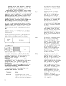
The EIB informs the program of data-check or
overrun conditions detected while the block of data
following bits in the Em:
Bit Position
4
5
Condition
Data Check
Overrun
The Em character is stored in the byte location
immediately following the ITB (or ETB or ETX)
character of the data block involved in the read
operation.
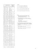
The ITB character is used to break up a long
record into shorter blocks; each block (except the
last) is ended with an ITB character. The direction
of transmission is not reversed following the ITB,
as it is following the ETX.
The record will end normally upon detection of
an ETB or ETX character. When the
text or transparent mode, DLE-Stick (followed by a
valid pad character) will end a read-type command
with Channel End and Device End status.
the defined DLE-Stick sequences are: ACK
will be treated like the NAK character.
Both characters must be of proper parity when
parity checking is performed. All DLE sequences
must be contiguous characters. If text mode is set,
the DLE-Control sequence will be treated as data
and included in the bcc accumuladon.
for two-way, nonsimultaneous (half-duplex), serial,
synchronous data communication over
switched transmission facilities having voice-grade
qualities. Information transmission (consisting
of data bytes, logical information, line-control
characters, error-checking characters, etc.)
consists of binary streams, serial by bit and by
stations operating over the data link may be
control units, or other equipment. For example,
two
over a communications path as shown in Figure 11.
The Synchronous Attachment is a prerequisite to
attaching any
Synchronous Bases can be installed in a
attachment of the Synchronous Attachment feature
in a
Expansion feature.
Operationally, the
channel program in conjunction with the data-link
control
via the communications network and the signals it
receives via the multiplexer channel attached to the
main-storage
station.
the
and control-character sequences and initiates
certain actions.
type commands and to the remote station on
write-type commands.
characters as r.equired.
to prevent system
looping.
The
reflecting the status of attached stations) via the
status and sense bytes. The program interrogates
each received response to determine if any further
action is required. For example, if:
--the remote station signals
mission).
--an attempt to transmit or recei'vc a data block
fails.
--erroneous or invalid characters are trans
ferred in either direction between main storage
and the
are received from the remote station.
--an error in sequencing of certain commands
occurs, or if invalid commands are attempted
to be executed.
--timeout conditions occur.