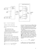
Code-conversion operations
Source-program information
Groups of short messages
Object-program information
Encrypted data
Unedited information
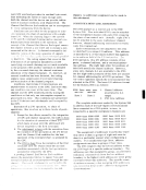
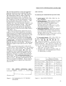
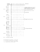
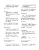
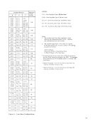
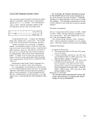
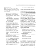
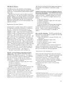
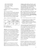
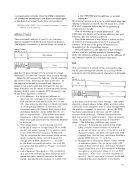
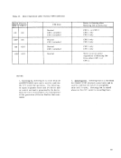
Transparency is provided as a standardfeature for EBCDIC and SBT. It is optionally available for USASCn. Transmission-Code Checking
The error-detection circuitry for each transmission
code is incorporated in the synchronous equipment.
Automatic-checking capability is provided for the
three transmission codes; however the checking
method employed depends on the Synchronous Ter
minal Control and the kind of transparency chosen.
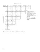
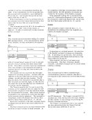
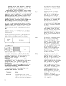
Table II indicates the checking methods available.
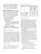
Table II. Transmission-Code Checking
Type of Checking
Transmission
No Transparency
Code
T ransparenc yInstalled and Installed Operating EBCDIC CRC-16 CRC-16 USASCII VRC/LRC CRC-16 SBT CRC-12 CRC-12
CRC = Cycl ic Redundancy check
VRC = Vertical Redundancy check
LRC = Longitudinal Redundancy check
TransparencyI nstalled But
Not Operating
CRC-16
VRC/CRC-16
CRC-12
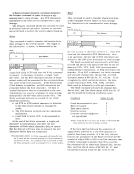
VRC/LRC. This transmission-error-detection
method consists of a combination of the vertical
redundancy check (VRC) and longitudinal redundancy
check (LRC). Thus, an odd VRC parity check is
performed on each transmitted character including
the LRC character. The LRC check is an even
longitudinal check on the total data bits (not in
cluding parity) of the transmitted block of characters
comprising the message block. The LRC is accumu
lated at both the sending station and the receiving
station during the block transmission. This accu
mulated value becomes the block-check character
(bcc). The trans mitted bcc is automatically
compared after ETX, ETB, or ITB with the bcc
accumulated at the receiving station for an equal
condition signifying correct receipt of the trans
mitted block.
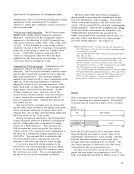
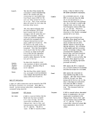
VRC/ CRC. This transmission-error-detection
method consists of a combination of a vertical
redundancy check and a cyclic redundancy check
(CRC). The CRC checking makes use of a circuit
implemented polynominal that treats the transmitted
message as a binarynU!llber, and performs modulo
2 divide operations on this binary number (carries
are not considered). Both the sendingand the recei
ving stations generate this value individually. The
transmitting station sends its generated value
resulting from the modulo 2 division.Only the
remainder is transmitted to the receiving station, at
which point the two CRe values are compared. Equal
comparison indicates accurate transmission.
CRC. This checking method, as outlined above,
The two variations of the polynominal (CRC16 and
CRC12 for eight-bit and six-bit codes respectively)
are included in the publication, General Information-
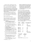
Binary Synchronous Communications, Form A27-3004. Synchronous Bases
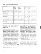
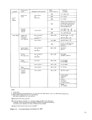
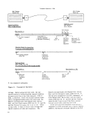
Three versions of Synchronous Bases are available:• Synchronous Base IA accommodates EBCDIC
orUSASCII at speeds up to 2400 bps. • Synchronous Base IB accommodates SBT, USASCII, or EBCDIC at speeds up to 2400 bps. • Synchronous Base 2A accommodates EBCDIC or USASCII at speeds up to 4800 bps.
Synchronous Base 1A permits the attachment of up
to 24 lines using EBCDIC orUSASCII terminal con
trols and operating at bit rates not exceeding2400 bits per second. This provides a character rate of
up to300 characters per second [(2400/8) = 300 characters]. Up to 600 digits per second can be
transmitted in packed-decimal.
Synchronous Base 1B permits the attachment of up
to 16 lines using EBCDIC,USASCII, or SBT terminal controls and operating at bit rates not
exceeding2400 bits per second. This provides a
character rate of up to400 characters per second
[(2400/6) = 400 characters] for SBT operation.
Synchronous Base 2A permits the attachment of up
to 12 lines using EBCDIC orUSASCII terminal con
trol and operating up to4800 bps. This provides a
character rate of up to600 characters per second (4800/8) = 600 characters or up to 1200 digits per
second in packed decimal.
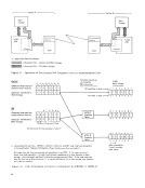
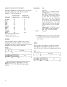
Synchronous LineSet Synchronous communications facilities are attached
to the2703, modular by four, via a Synchronous
LineSet. Each line set services up to four facilities
(half- or full-duplex). The maximum number of line
sets per Synchronous Base I depends on the trans-
mission code employed and whether the Synchronous
Clock feature is provided.
53
Source-program information
Groups of short messages
Object-program information
Encrypted data
Unedited information
Transparency is provided as a standard
The error-detection circuitry for each transmission
code is incorporated in the synchronous equipment.
Automatic-checking capability is provided for the
three transmission codes; however the checking
method employed depends on the Synchronous Ter
minal Control and the kind of transparency chosen.
Table II indicates the checking methods available.
Table II. Transmission-Code Checking
Type of Checking
Transmission
No Transparency
Code
T ransparenc y
CRC = Cycl ic Redundancy check
VRC = Vertical Redundancy check
LRC = Longitudinal Redundancy check
Transparency
Not Operating
CRC-16
VRC/CRC-16
CRC-12
VRC/LRC. This transmission-error-detection
method consists of a combination of the vertical
redundancy check (VRC) and longitudinal redundancy
check (LRC). Thus, an odd VRC parity check is
performed on each transmitted character including
the LRC character. The LRC check is an even
longitudinal check on the total data bits (not in
cluding parity) of the transmitted block of characters
comprising the message block. The LRC is accumu
lated at both the sending station and the receiving
station during the block transmission. This accu
mulated value becomes the block-check character
(bcc). The trans mitted bcc is automatically
compared after ETX, ETB, or ITB with the bcc
accumulated at the receiving station for an equal
condition signifying correct receipt of the trans
mitted block.
VRC/ CRC. This transmission-error-detection
method consists of a combination of a vertical
redundancy check and a cyclic redundancy check
(CRC). The CRC checking makes use of a circuit
implemented polynominal that treats the transmitted
message as a binary
2 divide operations on this binary number (carries
are not considered). Both the sending
ving stations generate this value individually. The
transmitting station sends its generated value
resulting from the modulo 2 division.
remainder is transmitted to the receiving station, at
which point the two CRe values are compared. Equal
comparison indicates accurate transmission.
CRC. This checking method, as outlined above,
The two variations of the polynominal (CRC16 and
CRC12 for eight-bit and six-bit codes respectively)
are included in the publication, General Information-
Binary Synchronous Communications, Form A27
Three versions of Synchronous Bases are available:
or
Synchronous Base 1A permits the attachment of up
to 24 lines using EBCDIC or
trols and operating at bit rates not exceeding
up to
transmitted in packed-decimal.
Synchronous Base 1B permits the attachment of up
to 16 lines using EBCDIC,
exceeding
character rate of up to
[
Synchronous Base 2A permits the attachment of up
to 12 lines using EBCDIC or
trol and operating up to
character rate of up to
second in packed decimal.
Synchronous Line
to the
Line
(half- or full-duplex). The maximum number of line
sets per Synchronous Base I depends on the trans-
mission code employed and whether the Synchronous
Clock feature is provided.
53