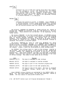
CALLED ROUTINE START-UP TABLE
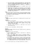
Figures 5 and 6 show how thePSW and registers are set up when the
called routine is entered.
rI "Called" Type System Mask 1--------------- ISVC 202 or 203 Disabled I - Nucleus I resi1ent 1--------------- -------------- ISVC 202 or 203 - Transient
areaMODULE SVC 202 or 203 - User area User- handled
as -DOS/VS Nucleus
resident
as -DOS/VS Transient
area module
Disabled
Enabled
Enabled
DisabledStorage Key Problem Bit System Off User Off User Off User Off System Off System Off Figure 5. PSW Fields When Called Routine Starts
,
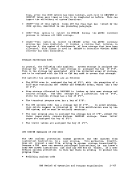
Registers RegisterslRegisterlRegister RegistertRegisterl
Type o -1 2 -111 12 I 13 14 I 15 I I I 1 I SVC 202 Same as Unpre- IAddress IUser Return 'Address I or 203 caller dictable I of I save address' of I I called I area to I called I , routine I , routine I ----I I I I other Same as Same as IAdd ress IUser Return ISame as I caller caller I of I save address I caller , 1 caller , area to , 1 I I I I Figure 6. Register Contents When Called Routine Starts RETURNING TO THE CALLING ROUTINE When the called routine finishes processing, control is returned to DMSITS, which in turn returns control to the calling routine.
The return is accomplished by leading the originalSVC old PSi (which
was saved at the timeDMSITS was first entered), after possibly modifying the address field. The address field modification depends upon the type of SVC call, and upon whether or not the called routine
indicated an error return.eftS Introduction 2-31
Figures 5 and 6 show how the
called routine is entered.
r
area
as -
resident
as -
area module
Disabled
Enabled
Enabled
Disabled
,
Registers RegisterslRegisterlRegister RegistertRegisterl
Type o -1 2 -11
The return is accomplished by leading the original
was saved at the time
indicated an error return.