1
2
3
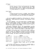
4-15ftegDi.ng If 1, this entry corresponds to a CSECT that has been previously
defined. AllTXT cards and RLD cards referring to this CSECT in
this text deck should be ignored.
If 1, this entry corresponds to aCSECT definition (SD). Waiting ESD itells exist for this ESDID. Unused. REFTBL entry number (for example 1, 2, 3, etc.)
Bit 1 is very crucial because it is necessary to use theVALUE field
of the REFTBL if the ID corresponds to an ER,Cft, or FR; but, the INFO field of the REFTBL entry must be used in the ID corresponds to an SD. REFTBI. EntA:Y I 10(0) - - - - - - HAftE 8 (8) 19 (9)
FLAG1, INFO I 12 (C) 113 (D) NOTEl I VALUE 1 16 (10) 117(11) FLAG2 1 ADDRESS A REFTBL entry is 20 bytes. The fields have the following uses: !AftE ESD data item.
Loader
7D
7E
7F80 81
82
8390 ESD 00 01 03 07 05 04 02 05 06 Routine XBYTE XfiALF XFULL XDBL XUNDEF XCXD XCOMSET iEAKEXT CTLLIB PR - byte alignment PR - halfword alignment PR - fullword alignment PR - doubleword alignment Undefined symbol
ResolveCXD Define common area
Weak external referenceTXTLIBs not to be used to resolve names !!FO ESD item. ESD Item SD (CSECT or START) LD (ENTRY) eft (COftMON) PR (Psuedo Register) INFO Field
Zero
Maximum length
2-84IBM VM/370 System Logic and Program Determination--Volume 2
2
3
4-15
defined. All
this text deck should be ignored.
If 1, this entry corresponds to a
Bit 1 is very crucial because it is necessary to use the
of the REFTBL if the ID corresponds to an ER,
FLAG1
Loader
7D
7E
7F
82
83
Resolve
Weak external reference
Zero
Maximum length
2-84