SYSTEM/360--I/0 OPERATION Input/output operations for the IBM 2703 are initiated
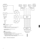
and controlled by information with two types of
formats: instructions and commands. Instructions
are decoded by the CPU and are part of the CPU program. Commands are decoded and executed
by the channels and I/O devices, and. initiate I/O operations, such as'reading and writing. One or
more commands arranged for sequential execution
form a channel program. Both instructions and
commands are fetched from main storage and are
common to all types of I/O devices, although the
modifier bits in the command code may specify
device-dependent conditions for the execution of a
data-transfer operation at the device.
The CPU program initiates 2703 I/O operations
with the Start I/O instructi<>n. This instruction
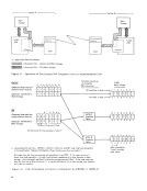
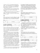
identifies the channel and the device, and causes the
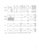
channel to fetch the channel-address word (CAW)
from a fixed location in main storage. The format
for the CAW is:
Command Address
o 3 4 78 31
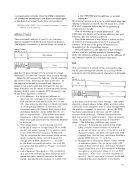
The CAW contains the protection key and designates
the location in main storage from which the channel
subsequently fetches the first channel-command
word (CCW). The CCW specifies the command to be
executed and the storage area, if any, to be used.
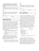
The format for the CCW is:
o
Command
Code
78
Data Address Flags I 000 32 36 37 3940 47 48
31
Count
63
If the subchannel associated with the addressed I/O device is not busy, the channel attempts to
select the dey ice by sending the address of the
device to all control units attached to the channel.
The control unit that recognizes the address connects
itself logically to the channel and responds to its
selection by returning its address. The channel
subsequently sends the command-code part of the
CCW oYer the interface, and the device responds
with a status byte indicating whether it can execute
the command.
DETAILED DESCRIPTION OF OPERATIONS NOTE: The 2703 does not operate in burst mode; neither can
the 2703 operate concurrently on the same channel with any
other device operating in burst mode.
At this time, the execution of Start I/O is term­
inated. The results of the attempt to initiate the
execution of the command are indicated by setting
the condition code in the program -status word (PSW) ,
and, under certain conditions, by storing pertinent
information in the channel-status word (CSW).
If the operation is initiated at the device and its
execution involves transfer of data, the subchannel is
set up to respond to service requests from the device
and assumes further control of the operation. In the
case of operations that do not require any data to be
transferred to or from the device, the device may
signal the end of the operation immediately on
receipt of the command code.
An I/O operation may involve transfer of data to
one storage area, designated by a single CCW, or to
a number of noncontiguous storage areas. In the
latter case, a list of CCW's is used for execution of
the I/O operation, each CCW designating a contiguous
storage area, and the CCW's are said to be cGupled by data chaining. Data chaining is specified by a
flag in the CCW and causes the channel to fetch
another CCW upon the exhaustion or filling of the
storage area designated by the current CCW. The
storage area designated by a CCW fetched on data
chaining pertains to the I/O operation already in
progress at the 2703, and the 2703 is not notified
when a new CCW is fetched. Provision is made in
the CCW format for the programmer to specify that,
when the CCW is decoded, the channel request an I/O interruption as soon as possible, thereby
notifying the CPU program that chaining has pro­
gressed to a particular CCW in the channel program.
Termination of the I/O operation normally is
indicated by two conditions: Channel End and Device
End. The Channel End condition indicates that the I/O device has received or provided all information
associated with the operation and no longer needs
channel facilities. The Device End signal indicates
that the I/O dev ice has terminated execution of thE operation. For the 2703, the Device End conditioL
always occurs concurrently with the Channel End
condition.
The conditions signaling the termination of an 110 operation can be brought to the attention of the
program by I/O interruptions. These conditions
cause storing the CSW, which contains additional
information concerning execution of the operation.
At the time the Channel End/Device End condition
is generated, the channel identifies the program the
11
last CCW used and provides its residual by'te count,
thus indicating the extent of main storage used.
Both the channel and the device can provide indica­
tions of unusual conditions with Channel End. The Channel End/Device End condition can be accompanied b,,' ('rror indications from the device.
Facilities are provided for the program to initi­ 'ite execution of a chain of operations with a single Start L o. When the chaining flags in the current ccw specify command chaining and no unusual con­
ditions have been detected in the operation, the
receipt of the Channel End/Device End signal causes
the channel to fetch a new CCW and to initiate a new
command at the devicc. A chained command is ini- Liated by iHeans of the same sequenCe of signals .j. 1 T / f \ !. -- 4- r - ('., r>. ,.." ,-, 1.-. n .f ""\< ... ,.. ... f rt ro, Y'V"I " "" r1 ,....., ... n ,... ; fi n rl ....1. ,. 1 " J .J. -" ,_-+ ". -_" ,.. £ "--- ..L -"-.. '-- _ _ --"" ...... ...... 1:_ -_ "-"" -=- -"- ........... by Start 1/ O. The ending signals that occur at the
termination of an operation initiated by a CCW specifying command chaining are not made available
to the program when another operation is initiated
by the command chaining; the channel continues
execution of the channel program. If, however, an
unusual condition has been detected, the ending
signals cause suppression of command chaining
and termination of the channel program.
Conditions that initiate I/O interruptions are
asynchronous to activity in the CPU, and more than
one condition can occur at the same time. The
channel and the CPU establish priority among the
conditions so that only one interruption request is
processed at a time. The conditions are preserved
in the I/O devices and subchannels until accepted by
the CPU. Execution of a 2703 operation, or chain of
operations, thus involves up to three levels of parti­
cipation:
1. Except for the effects caused by the integration
of CPU and channel equipment, the CPU is busy
for the duration of execution of Start I/O, which lasts at most until the addressed I/O device responds to the first command.
2. The subchannel is busy with the execution from
the initiation of the operation at the I/O device
until the Channel End condition for the last
operation of the command chain is accepted by
the CPU. 3. The 2703 is busy from the initiation of the first
command until the Channel End/Device End condition associated ''lith the last oppration is
accepted or cleared by the CPU. A pendlllg Channel End/Device Enu vunuition eauses the associated device to appear busy and normaE,; blocks all communications through the sub- l" ("<ich ,;!_;1)channel i"O to thE' ; ()ncC' 1 (' the sub- channel, no additional assignment can be made to
this subchannel. COMMUNICA TIONS- LINE ADDRESSING
The 2703 appears as a control unit to the IBM System/360. Two individual 2703's can be attached
to the multiplexer channel with each 2703 occupying
the place of one control unit. Actuallv, eight 2703' s
can be attached to the same multiplexer channel;
however, channel-addressing restrictions normally
make this impractical.
Each communications line attached to the 2703 is identified by a unique I/O address. This address
is specified by a H>-bit binary number that appears
. " , " ", r 11 T Jr-,. i ," 111 aUuJ"e>::>::, 11l:1U U1 Llle v 11l>::>Ll UCLHJi1. Vi 2703 operation, this I/O address consists of two
parts: a channel address, and a communications­
line address. The eight high-order bit positions of
this field specify the channel address. However,
since only channels 0-6 are available to the 2703, the five high-order positions of this byte are unused
for channel addressing for all 2703 operations. The
low-order eight bits specify the communications line
attached to the 270-3. The basic I/O-address format
for the System/360 is as follows: 0000 Oxxx xxxx xxxx Byte 1 Byte 2
1. Channel Address
(restricted to 0-6 range)
2. 2703 Line Address
The complete addresses needed by the System/360
to address each of ten half-duplex communications
lines connected to a 2703 (which, in turn, is
connected to a specific multiplexer channel) are: 0000 Oxxx 0000 0000 0000 Oxxx 0000 0101 0000 Oxxx 0000 0001 0000 Oxxx 0000 0110 0000 Oxxx 0000 0010 0000 Oxxx 0000 0111 0000 Oxxx 0000 0011 0000 Oxxx 0000 1000 0000 Oxxx 0000 0100 0000 Oxxx 0000 1001 The assignment of addresses to particular start/
stop lines is done in groups of eight and must be
done in a particular manner when configurating a
system. For synchronous type lines, address are done in groups of four lines.
The 2703 requires that the lowest address within thp hpP'in at a sDecific address boundary. The -:re then by group, as previously
indicated, consecuti"vely from the low-address
boundary to the highest valid address (or some group
increment below this address). The specific cons ckrations necessary \yhen assigning 270:3 addresses arc coycrcd in detail under "Addrpss-Assignment Considerations. " I
Previous Page Next Page