mand at the addressed MCW is terminated, the
proper status information is returned to the channel.
If the current command is Write, the character
being transmitted and the character buffered, if
present, are sent before Channel End and Device End
status are presented to the channel. A maximum
three-character delay (up to500 ms) can occur
between the time the HaltI/O is accepted and the
presentation of Channel End and Device End status to
the channel.
TestI/O The 2703 responds unconditionally to an all-zero
command byte during initial command selection
with the status-modifier bit of the status byte. Any
existing interrupt conditions in the2703 are not
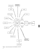
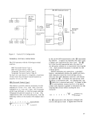
cleared; the multiplexer channel remains unchanged.PROGRAMMING CONSIDERA TIONS From a programming standpoint, the 2703 appears
as a number of individual communications-control
devices. When an operation or sequence of opera
tions is to be performed, the programmer prepares
a list of one or more channel-command words
(CCW's) in main storage. (Refer to"System/360- I/O Operation" earlier in this manual for the format
of the CCW.) The channel-command word specifies:
1. The command (operation) to be performed
(Write, Dial, Read, etc.).
2. The number of bytes contained in the record.
3. The address in main storage where data is to
be placed when receiving, or the address of
the first byte to be transmitted when sending.
4. Command flags to control possible modifica
tion in command execution. The flags are:
chain data, chain command, suppress length,
skip, and program-controlled interruption.
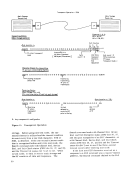
When the CCW's have been formed, the pro
grammer specifies the channel and line address of
the communications line. The execution of a
StartI/O instruction causes the command, count,
data-address, and control information to be stored
in a specified subchannel within the multiplexer
channel. The channel thenselectci the 2703 and
relays the command and line address to it; the2703 accepts the command if valid. The channel then
indicates successful or unsuccessful execution of
the StartI/O instruction to the program. Once a command has been accepted by the multi
plexer channel and the2703, the CPU program is
unaware of the
message has been received or transmitted, or until
the multiplexer channel requires interruption either
to perform functions such as dynamic storage allo-
cation or because an unusual condition is detected
during execution. Since the multiplexer channel
contains all the necessary information pertaining to
the current operation, data transfer between main
storage and the2703 can be overlapped with CPU processing. The extent of the overlap varies,
depending on the processor model(30, 40, 50, 65,
or 75) of System/360.
If the2703 is reset, either by a general system
reset, by a power-on reset, or individually at the
CE panel, the communications line must be enabled
by issuing the Enable command where necessary.
This command must be issued before transmitting
in all cases except for a link using a half-duplex data
set or an IBM Line Adapter.
The following2703 functions require special
programming considerations:
1. The2703 signals Control Unit Busy in response
to initial selection when the interface registers
are in use with a previous command cycle or
when the2703 is executing a machine reset
resulting from a system reset or power-on
reset. The2703 responds to the interface
signals, Address Out and SelectOut, and to
a valid address on BusOut with the interface
tag, Status In, and to the busy, status-modifier,
and control-unit-endbitQ on Bus In.
2.On an end-of-transmission sequence, when a © is sent under the Write command to a
private line using a common-carrier data set
with an IBM Terminal Control Type I or II, at
least two additional consecutive@ 's must be
sent by the program. This prevents receiving
a false start bit, generated by the remote data
set, when the terminal turns off its Request to
Send lead.
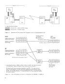
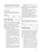
Automatic Wraparound
The automatic-wraparound (autowrap) capability is a
standard feature of the2703 and can be utilized by
the program to determine the source of error for a
given2703 line. The wraparound function is initiated
by issuing the Wrap command to the2703 line address
on which trouble is suspected.
The2703 wraps the output of the line to which the
Wrap command is issued to the input of the linev'ith the lowest address within this 2703. Wraparound is
accomplished within the line adapter to avoid line
termination mismatches, since the line with the
lowest line address is not necessarily the same type
of line as the line being tested. The execution of
Wrap is always one way; that is, the transmit
operation is performed on the line in question and the
receive operation on the lowest line address. A Read
command must be issued to the low line address be-
15
proper status information is returned to the channel.
If the current command is Write, the character
being transmitted and the character buffered, if
present, are sent before Channel End and Device End
status are presented to the channel. A maximum
three-character delay (up to
between the time the Halt
presentation of Channel End and Device End status to
the channel.
Test
command byte during initial command selection
with the status-modifier bit of the status byte. Any
existing interrupt conditions in the
cleared; the multiplexer channel remains unchanged.
as a number of individual communications-control
devices. When an operation or sequence of opera
tions is to be performed, the programmer prepares
a list of one or more channel-command words
(CCW's) in main storage. (Refer to
of the CCW.) The channel-command word specifies:
1. The command (operation) to be performed
(Write, Dial, Read, etc.).
2. The number of bytes contained in the record.
3. The address in main storage where data is to
be placed when receiving, or the address of
the first byte to be transmitted when sending.
4. Command flags to control possible modifica
tion in command execution. The flags are:
chain data, chain command, suppress length,
skip, and program-controlled interruption.
When the CCW's have been formed, the pro
grammer specifies the channel and line address of
the communications line. The execution of a
Start
data-address, and control information to be stored
in a specified subchannel within the multiplexer
channel. The channel then
relays the command and line address to it; the
indicates successful or unsuccessful execution of
the Start
plexer channel and the
unaware of the
message has been received or transmitted, or until
the multiplexer channel requires interruption either
to perform functions such as dynamic storage allo-
cation or because an unusual condition is detected
during execution. Since the multiplexer channel
contains all the necessary information pertaining to
the current operation, data transfer between main
storage and the
depending on the processor model
or 75) of System/360.
If the
reset, by a power-on reset, or individually at the
CE panel, the communications line must be enabled
by issuing the Enable command where necessary.
This command must be issued before transmitting
in all cases except for a link using a half-duplex data
set or an IBM Line Adapter.
The following
programming considerations:
1. The
to initial selection when the interface registers
are in use with a previous command cycle or
when the
resulting from a system reset or power-on
reset. The
signals, Address Out and Select
a valid address on Bus
tag, Status In, and to the busy, status-modifier,
and control-unit-end
2.
private line using a common-carrier data set
with an IBM Terminal Control Type I or II, at
least two additional consecutive
sent by the program. This prevents receiving
a false start bit, generated by the remote data
set, when the terminal turns off its Request to
Send lead.
Automatic Wraparound
The automatic-wraparound (autowrap) capability is a
standard feature of the
the program to determine the source of error for a
given
by issuing the Wrap command to the
on which trouble is suspected.
The
Wrap command is issued to the input of the line
accomplished within the line adapter to avoid line
termination mismatches, since the line with the
lowest line address is not necessarily the same type
of line as the line being tested. The execution of
Wrap is always one way; that is, the transmit
operation is performed on the line in question and the
receive operation on the lowest line address. A Read
command must be issued to the low line address be-
15