23 24
47 48 SS S6
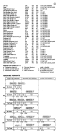
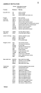
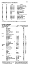
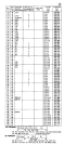
13 Machine check mask (M)
14 Wait state (W)
15 Problem state (P)
31
63
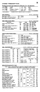
o Channel
1 Channell mask
2 Channel 2 mask
3 Channel 3 mask
4 Channel 4 mask
5
32-33
6 Mask for channel 6 and up
7 External mask
12
36 F ixed-point overflow mask
37 Decimal overflow mask
38 Exponent underflow mask
39 Significance mask
*A one-bit equals on, and permits an interrupt.
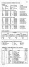
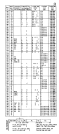
CHANNEL
o 3 4 7 8
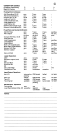
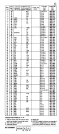
CHANNEL COMMAND
Byte Count
CC-bit 33
SLI-bit 34
Skip-bit 35
0 3 4 7 8
1
24
32
1
40
31
63
31
63
33 (4000) Status modifier 41
34 (2000) Control unit end 42
35
36
37
38
39
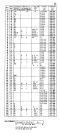
Byte Count: bits 48-63 form the residual count for the
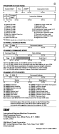
Comments about this card may be sent to the Technical Pub
lications Department at the White Plains address
Data
1133 Westchester Ave., White
821 United Nations