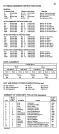
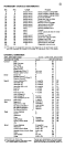
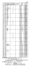
16
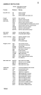
24 18 double word External
64 40 double word Channel status word
72 48 word Channel address word
76 4C word Unused
84 54 word Unused
88 58 double word External new PSW
96 60 double word
112
(1) The size of the diagnostic scan-out area depends on the
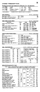
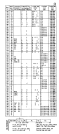
CHANNE L
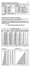
Set File Mask 1 1F
Restore (2321 only) Not zero 17
Reserve
Key
Key
Key
Key & Data
Key & Data
Key & Data
Continue
25 A5
45 C5
65 E5
mask bytes.
35 85
Set
No
feature.)
55
Count 8 12 92
Record
Data
}
Number
Key & Data of bytes
Count, Key & Data transferred 1E 9E
Record
Count, Key & Data 8+KL+DL
Erase 8+KL+DL 11
1. For 2311 or 2314
2.