lure autowrap is started in order to permit the data Wrap command to be received. 'l 'Yrap to any communications line on the 2703. The i'-l'dlIl must not issue Wrap to more than one
,.tt l( '" :'--b':-character comparison of re- , .; I d rlata with transmitted data and/or monitor the " J'ation for recognizable control characters.
The low line is not reserved as a test line, but is
used during the autowrap process. (However, it
should be recognized that the low line itself canne\'cr be issued a Wrap command.) Since the low :: '\'.?y::tparolJnd opcratiC'ns, the auto-
wrap operation selects the proper terminal control
so that this low line operates as if it were the same
kind of communications line as the line being tested.
In this \vay, a complete check is made of the common
controls and storage as well as the terminal control
of the line in question. Receive operations are
checked because a common terminal control performs
the work.NOTE: Output data can be blocked from going onto the
communications lineuy issuing the Disable command to
the2703 line just before the Wrap is issued.
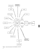
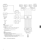
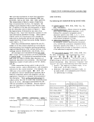
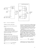
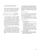
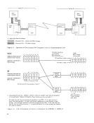
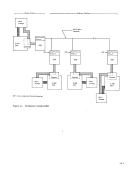
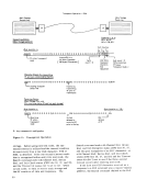
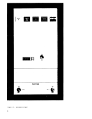
2703Common Controls The common-controls-and-storage section of the 2703 contains the storage
common to all lines and line bases (see Figure 3).Common controls stores the I/O commands and data
bytes, assembles the line-base data bits into charac
ters, and disassembles characters in to line-base
data bits.
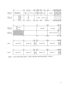
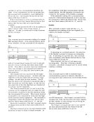
Four 36-bit words are reserved for each possible
line address. These words are:
MainControl Word 1 (MCW-l) Main Control Word 2 (MCW-2) Main Data Word 1 (MDW-l) Main Data Word 2 (MDW-2)--used exclusively
for synchronous operation
The main control words contain the control infor
mation necessary for the 2703 to know exactly where
it is when sequencing through its operations. They
also store status and sense information. The maindata worns each provide four character buffers for
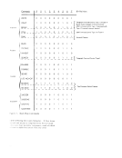
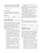
data transfer to and from the channel. Thesecontrol and data \vords (Figure 4) allO\v t!1e 2703 to
multiplex the operation of up to 176 transmission
lines\\'Hh one transmission control unit.
The field assignments within the control wordsdiffer slightly between start/stop and S}11Chronous ty1)e operations as indicated by Figure 4. These
differences are described underMCV/-l and MCW-2. 16
The field assignments for the data words are identi
cal for both types of operation.
MainControl Word 1 MCW-l stores the operating controls for its
associated line and the data character that is being
assembled or disassembled.
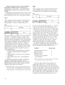
Assemble/Disassemble Field. The assemble/
disassemble (A/D) field stores the data byte being
transmitted or received. Data in the A/D field can
be shifted left one bit position at a time.On a receive operation (for start/stop), the bits in the A/D field are shifted left one position, and the
line-base data bit is inserted into bit-position 7.On a transmit operation (for start/stop), the
high-order bit of the A/D field character is sent to
the line base, and the A/D bits are shifted left one
position.
On a timeout operation, the A/D field is used as
a count
tween characters. For example: The 2703 is
receiving text froma 1050 terminal and the 1050 operator fails to send EOB (end of block) following
the last character; a timeout operation allows the
2703 to end the receive operation 28 seconds after
receiving the last character.
For synchronous type operations, bits 4 and 5
within the A/D field are used for data-check and
overrun indication when receiving in intermediate
block (ITB) mode. These conditions are set in the
error-indicator byte (EIB) following an ITB, ETB
(end of transmission block), or ETX (end of text)
generated by the 2703 while executing the Read
command in ITB mode. Data check can also be set
while the 2703 is monitoring the line in the absence of
a command, so that once a command is accepted the
data-check bit is set in the sense byte withinMCW-2. During a transmit operation the A/D field acts as a
character buffer, buffering the next character to be
transferred to the Synchronous Line Base for trans
mission.
Character Address. In a Read command this ad
dress refers to the position in theMDW to which the
A/D field will be transferred when a character has
been assembled. Similarly, in aWrite operation,
this address refers to the next character to be taken
from the MDW-l, or MDW-2, and placed in the
A/D field.
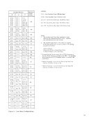
BitCount. This counter increments as the AID field obtains more bits from the start/stop line base,
or sends bits to the start/stop line base.When this
count reaches a specific number setby the terminal
,
The low line is not reserved as a test line, but is
used during the autowrap process. (However, it
should be recognized that the low line itself can
wrap operation selects the proper terminal control
so that this low line operates as if it were the same
kind of communications line as the line being tested.
In this \vay, a complete check is made of the common
controls and storage as well as the terminal control
of the line in question. Receive operations are
checked because a common terminal control performs
the work.
communications line
the
2703
common to all lines and line bases (see Figure 3).
bytes, assembles the line-base data bits into charac
ters, and disassembles characters in to line-base
data bits.
Four 36-bit words are reserved for each possible
line address. These words are:
Main
for synchronous operation
The main control words contain the control infor
mation necessary for the 2703 to know exactly where
it is when sequencing through its operations. They
also store status and sense information. The main
data transfer to and from the channel. These
multiplex the operation of up to 176 transmission
lines
The field assignments within the control words
differences are described under
The field assignments for the data words are identi
cal for both types of operation.
Main
associated line and the data character that is being
assembled or disassembled.
Assemble/Disassemble Field. The assemble/
disassemble (A/D) field stores the data byte being
transmitted or received. Data in the A/D field can
be shifted left one bit position at a time.
line-base data bit is inserted into bit-position 7.
high-order bit of the A/D field character is sent to
the line base, and the A/D bits are shifted left one
position.
On a timeout operation, the A/D field is used as
a count
tween characters. For example: The 2703 is
receiving text from
the last character; a timeout operation allows the
2703 to end the receive operation 28 seconds after
receiving the last character.
For synchronous type operations, bits 4 and 5
within the A/D field are used for data-check and
overrun indication when receiving in intermediate
block (ITB) mode. These conditions are set in the
error-indicator byte (EIB) following an ITB, ETB
(end of transmission block), or ETX (end of text)
generated by the 2703 while executing the Read
command in ITB mode. Data check can also be set
while the 2703 is monitoring the line in the absence of
a command, so that once a command is accepted the
data-check bit is set in the sense byte within
character buffer, buffering the next character to be
transferred to the Synchronous Line Base for trans
mission.
Character Address. In a Read command this ad
dress refers to the position in the
A/D field will be transferred when a character has
been assembled. Similarly, in a
this address refers to the next character to be taken
from the MDW-l, or MDW-2, and placed in the
A/D field.
Bit
or sends bits to the start/stop line base.
count reaches a specific number set