control, the data in the A/D field is transferred to
the MDW-1, or MDW-2, during a Read operation;
or, during aWrite operation, the data in MDW-1,
or MDW-2, is transferred to the A/D field. This
counter ensures that each line in the 2703 never
requests data service in less than two character times,
for any synchronous operation.
For synchronous operations this counter is also
used for counting the time betweenWrite commands
while in transparency. In addition, it is used during
receiving to count for the one-second and three
second receive time outs .
Timeout. The timeout bits are set during a line
timeout and define the type of timeout condition
occurring.
Shift. The shift bit indicates an upper-case charac
ter in the A/D field. It is set toON when the A/D
field receivesa. shift character or transmits a
character with a shift bit. This field is assigned as
an additional position in the mode field for synchron-
ous type operations.
line is in text-out, text-in, poll, control, transparent,
or intermediate-block mode.
Sequence. The sequence field defines the operation
to be carried out on the character in the A/D field.
For synchronous operations, this field is extended
to four bits by assigningbIt 24 as part of this field.
IBM. This is used only for synchronous operationstoj;dicate ,"vhen the line is in intermediate-block
mode. A Set Mode command turns thisON, and it
is reset by either a Disable command or by another
Set Mode command when the Bus Out-one position
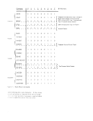
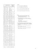
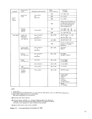
is zero.Command. The command field stores the program
commands in abbreviated form (the five low-order
bits modified from the command, see Figure 7).
Data Service. The data-service bit signals the1/0- interface circuits to transfer data bytes between
MDW-l, or MDW-2, and the multiplexer channel.
18
During a transmit operation, data service is set
for MDW-1 when the last character leavesMDW-1 (for start/stop operations). For synchronous opera
tions,MDW-1 is set for data service when the first
character leaves MDW-2, whileMDW-2 is set for
data service when the first character leaves MDW-l.
During a receive operation, data service is set when
MDW-1, or MDW-2, contains four data bytes (or
fewer, on end-of-opcration).
End. The end bit signals theI/O interface to send
the ending-status byte to the multiplexer channel.
Halt/Stack. The halt/stack bit indicates one of the
following has occurred:
1. The line has received a HaltI/O command
from the channel during a transmit operation.
2. The line has received a HaltI/O command or
a Stop signal from the channel during a re
ceive operation.
3. The channel was unable to accept either the
initial- or the ending-status byte and has
requested that status be stacked.
This bit indicates a HaltI/O when the end bit is OFF, and it indicates Stack when the end bit is ON. Receive. The receive bit is turned ON when the 2703
is receiving data on the associated transmission line.
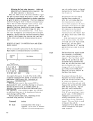
Parity. This bit is set to provide odd parity forMCW-1. Main Control Word 2 MCW-2 (see Figure 4) stores the check character,
sense byte, and status byte for its associated line.LRC Check Character. The LRC-check-character
field holds the check character as it is being developed
during data transmission. For synchronous
operations, this field is unassigned.
Sense Byte. The sense-byte field contains the sense
information to be presented to the channel upon
receipt of a Sense command. (See "Sense-ByteConditions!! under "Commands. ")
the MDW-1, or MDW-2, during a Read operation;
or, during a
or MDW-2, is transferred to the A/D field. This
counter ensures that each line in the 2703 never
requests data service in less than two character times,
for any synchronous operation.
For synchronous operations this counter is also
used for counting the time between
while in transparency. In addition, it is used during
receiving to count for the one-second and three
second receive time outs .
Timeout. The timeout bits are set during a line
timeout and define the type of timeout condition
occurring.
Shift. The shift bit indicates an upper-case charac
ter in the A/D field. It is set to
field receives
character with a shift bit. This field is assigned as
an additional position in the mode field for synchron-
ous type operations.
line is in text-out, text-in, poll, control, transparent,
or intermediate-block mode.
Sequence. The sequence field defines the operation
to be carried out on the character in the A/D field.
For synchronous operations, this field is extended
to four bits by assigning
IBM. This is used only for synchronous operations
mode. A Set Mode command turns this
is reset by either a Disable command or by another
Set Mode command when the Bus Out-one position
is zero.
commands in abbreviated form (the five low-order
bits modified from the command, see Figure 7).
Data Service. The data-service bit signals the
MDW-l, or MDW-2, and the multiplexer channel.
18
During a transmit operation, data service is set
for MDW-1 when the last character leaves
tions,
character leaves MDW-2, while
data service when the first character leaves MDW-l.
During a receive operation, data service is set when
MDW-1, or MDW-2, contains four data bytes (or
fewer, on end-of-opcration).
End. The end bit signals the
the ending-status byte to the multiplexer channel.
Halt/Stack. The halt/stack bit indicates one of the
following has occurred:
1. The line has received a Halt
from the channel during a transmit operation.
2. The line has received a Halt
a Stop signal from the channel during a re
ceive operation.
3. The channel was unable to accept either the
initial- or the ending-status byte and has
requested that status be stacked.
This bit indicates a Halt
is receiving data on the associated transmission line.
Parity. This bit is set to provide odd parity for
sense byte, and status byte for its associated line.
field holds the check character as it is being developed
during data transmission. For synchronous
operations, this field is unassigned.
Sense Byte. The sense-byte field contains the sense
information to be presented to the channel upon
receipt of a Sense command. (See "Sense-Byte