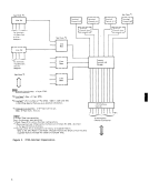
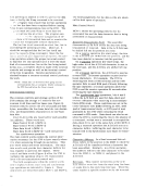
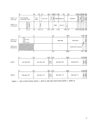
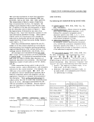
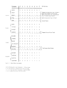
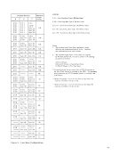
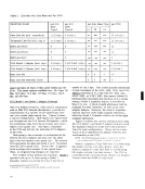
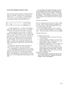
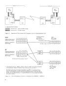
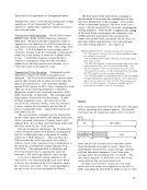
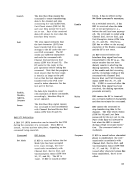
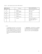
Synchronous
MCW-2 for
Synchronous
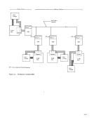
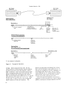
a
a
a
a
a
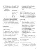
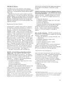
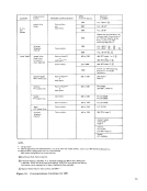
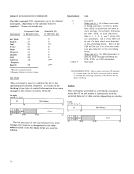
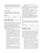
Char
Addr
:u:
26
31 32 33 34 35
u
u
LRC
Check Char
Data Byte
7 8 15
Data Byte
7 8 15
Data Byte
18
16 17 18
Char.
Count
Data Byte
Char.
Data Byte
25 26 33 34 35
25 26 33 34 35
Data Byte 111
17


Powered by Tizra® |