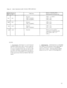
ending-status information that is presented to the
channel at the completion of the command.
error is detected during an access to
is reset; Equipment Check is then set to indicate the
occurrence of a core-storage parity error.
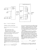
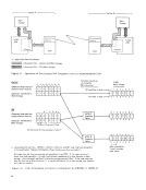
bytes for receive or transmit type operations. Data
is transferred to and from the channel in bursts of
up to four bytes to reduce I/O-interface time.
operation3 are performed.
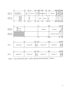
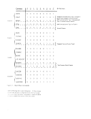
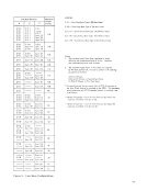
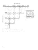
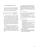
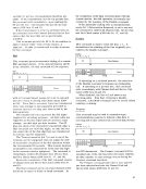
Data Byte. The eight data-byte fields store the
channel data bytes.
defines the number of characters received from the
channel on a transmit data service, or the number
of characters to be sent to the channel on a receive
data service. The character count in conjunction
with the condition of the data bit
cates the full or empty condition of the main data
words for a transmit operation.
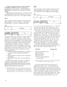
Data. The data bit is set
The data bit
means there is no data in
for
data ope ra tions .
each main data word
offered for the
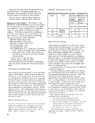
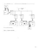
three distinct groups: general--pertaining to both
start/ stop and synchronous type operations; start/
stop type operations exclusively; and synchronous
type operations exclusively. The feature number is
provided with each feature as a means of positive
identification, as well as for future reference
purposes.
In addition, the features within the general group
are described in detail. For detailed information
pertaining to features exclusive to either start/stop
or synchronous operations, check the special
features paragraphs in the start/stop and synchronous
portions of this manual.
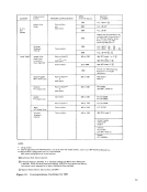
General (both
eight lines)
Autocall, second--#1341 (Automatic calling for an
additional eight lines)
Two-
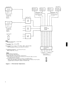
Terminal-Control Features
IBM Terminal Control Base--#4619 (for Terminal
Control Type I and II)
IBM Terminal Control Type 1--#4696 (for
2741 Break--#8055 (for 2741 with Interrupt feature)
Type I Terminal Interrupt--#8200 (for either IBM
1
Communication Terminals equipped with Interrupt
features)
IBM Terminal Control Type II--#4697 (for
Telegraph Terminal Control Type I and II and
for
Telegraph Terminal Control Type 1--#7911 (for
AT&T 83B2/83B3 or
terminals)
Telegraph Terminal Control Type II--#7912 (for
Model 33/35
(for
Telegraph Attachment--#7876 (to attach Telegraph
Line
Base Expansion--#1440 (to attach more than one
Data Line
carrier data sets--for
Data Line
lines)
19