TEST ASSEMBLE Al - F 80 (1) ALT=14 RECDS 20 ===)-{JP 5' --" PROGRAM START 0 BEGIN CONTROL SECTION /===/ USING PROGRAM.RlS
*===* STM R14.R12.ZERO(R13) *===*
LA R13.0URSAVE
*===*
XR R2.R2
*==:;*
R3.=F'lO'
*===*
R2.=F'S'
*===*
M R2.=F'lO'
*===*
LR RlS.R2
*===* ST RlS.Rl*FOUR(R13)
*===*
. RS.=F'lOO' *===*
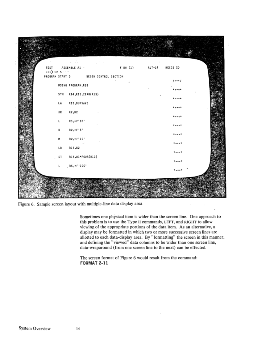
Figure 6. Sample screen layout with multiple-line data display area
System Overview 14
Sometimes one physical item is wider than the screen line. One approach to
this problem is to use the Type II commands, LEFT, and RIGHT to allow
viewing of the appropriate portions of the data item. As an alternative, a
display may be formatted in which two or more successive screen lines are
allotted to each data-display area. By "formatting" the screen in this manner,
and defining the "viewed" data columns to be wider than one screen line,
data-wraparound (from one screen line to the next) can be effected.
The screen format of Figure 6 would result from the command:
FORMAT 2-11
Screen Order of Processing
The last eight positions of each data-display area contain the Type III com­
mand line for that data-display. Type III commands are used to .perform functions for each individual data-display (see Type III Edit..: .
ing Commands in Section IV).
Optionally, the user may specify (using the FORMAT command) that the given
logical display is not to contain Type III command areas, permitting full
screen-width viewing. However, users should avoid, whenever possible,
eliminating the Type III areas since these are used as physical line separation
fields on the 3270. Elimination of these fields will cause substantially in­
creased communication overhead (especially on remote devices) and seriously
complicate cursor movement and positioning.
Each data-display area normally contains the "viewed" columns of one
data-item in the file (see the VIEW command in Section IV). However:· a line
may also contain the "TOP-OF-FILE" or "END-OF-FILE" indicators (example on
line 24 in figure 3). These lines do not become part of the file on disk and
any changes to these lines or their corresponding Type III areas are ignored.
The order of processing for the screen is of prime importance because it
determines the net effect of entering multiple commands and various changes
to the display. First the "FILEID" area of the screen is examined for change.
Then each logical display is processed, in order, from the top of the screen to
the bottom. The processing of each logical display consists of: 1) scanning
each data-display area and recording any modifications made, therein; 2)
processing the Type III command for the given data-display area (if Type III
commands exist) immediately after recording any changes to that display; 3)
processing the Type I & II command area; and 4) performing any "post­
processing" (see Section IV) necessitated by Type I commands.
When all display processing is complete, the "alteration count" is inspected to
see whether an "AUTOSAVE" is necessary (if that option is in effect). If
required, the file is checkpointed before the "set-up" of the new display
begins. When all of the above processing has been completed, a new display
is constructed and the logical screen is returned to the I/O Processor. System Overview 15
Previous Page Next Page