for a virtual machine if the virtual-machine assist is
activated for this instruction, unless (1) a virtual
machine exception is recognized, (2) the real page
size is 2K bytes, or (3) some pertinent
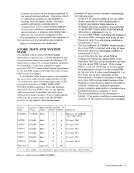
The set-storage-key function of the virtual
machine assist is invoked each time a
to execute a SET
when the problem-state bit of the real PSW is one.
Execution of this function consists in performing
the following steps:
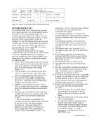
1. Execution of this function ends with a program
interruption for a privileged-operation
exception if bits
not
register specified by the R2 field of the
instruction are not zeros (1).
2. The word MICRSEG, which contains the real
segment-table address, is fetched with a key of
zero. Execution ends if an addressing
condition is encountered (2).
3. Execution ends with a program interruption for
a privileged-operation exception if bit
MICRSEG is one (3).
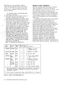
4. The address in the general register specified by
the R2 field is partitioned to obtain the segment
index and the page index. The partitioning of
the address is based on 4K-byte pages and
either 64K-byte or 1M-byte segments,
depending on whether bit 31 of MICRSEG is
zero or one, respectively. For a 64K-byte
segment, execution ends with a program
interruption for a privileged-operation
exception if the segment-table-length value in
bit positions
value obtained by appending four zeros to the
left of bits 8-11 of the address specified (4).
5. The address of the real-segment-table entry,
SEGPAGE, is computed, and the entry is
fetched with a key of zero. Execution ends if
an addressing condition is encountered (5).
6. Execution ends with a program interruption for
a privileged-operation exception if the
segment-table entry is invalid, if the entry has
an invalid format, or if the value of the
leftmost four bits of the page index exceeds the
value of bits
(6).
7. The location of the swap-table address is
computed by subtracting 4 from the page-table
origin derived from the segment-table entry.
18 Virtual-Machine Assist and Shadow-Table-Bypass Assist
The word at this location,
with a key of zero. Execution ends if an
addressing condition is encountered (7 .A. 1).
of the swap-table-address word to obtain the
address of the swap-table word. The swap
table word at the address computed is fetched
with a key of zero. Execution ends if an
addressing condition is encountered. SWPFLG,
and 3 of the word fetched (7.A.2).
9. Twice the page index is added to the page-table
origin from the segment-table entry to obtain
the address of the page-table entry. The page
table entry,
of zero. Execution ends if an addressing
condition is encountered (7 .B.1).
a privileged-operation exception if the page
table entry is valid and has an invalid format
(7.B.2).
11. If the page-table entry is valid, the reference
and change bits are fetched from the real
storage key, and a new value is placed in the
real storage key. Execution ends if an
addressing condition is encountered. Bits
positions 24-28 of the general register specified
by R2 field of the instruction. Bits 5 -6 (the
reference-bit and change-bit positions) of the
new value are zeros. If the page-table entry is
invalid, execution continues as if real
reference-bit and change-bit values of zero had
been fetched (7.B.3).
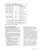
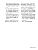
12. The swap-table word previously fetched is
updated in storage, with a key of zero, by
computing new values of
reference-bit and change-bit values are updated
by logically
of the real reference-bit and real change-bit
values, respectively. In addition, bits
swap-table byte containing the virtual storage
key are replaced by bits
register specified by the R2 field of the
instruction. Bit 7 of that byte is set to an
unpredictable value. The swap-table word
contains two sets of backup bits and virtual
storage-key bytes. The value in bit position
specified by the R2 field of the instruction
determines which set is used in this step.
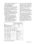
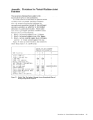
Figure 13 shows the bit positions of the bits
and byte used (8).