an invalid format, or if the value of the
leftmost four bits of the page index exceeds the
value of bits0-3 of the segment-table entry
(4 ).
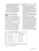
8. The location of the swap-table address is
computed by subtracting 4 from the page-table
origin derived from the segment-table entry.
The word at this location, P AGSWP, is fetched
with a key of zero. Execution ends if an
addressing condition is encountered (S.A.l).
9. Eight times the page index is added to bits 8-31
of the swap-table-address word to obtain the
address of the swap-table word. The swap
table word at the address computed is fetched
with a key of zero. Execution ends if an
addressing condition is encountered. SWPFLG,SWPKEYl, and SWPKEY2 are in bytes 0, 2,
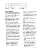
and 3 of the word fetched (S.A.2).10. Twice the page index is added to the page-table
origin from the segment-table entry to obtain
the address of the page-table entry. The page
table entry,PAGCORE, is fetched with a key
of zero. Execution ends if an addressing
condition is encountered (S.B.l).
1 1. Execution ends with a program interruption for
a privileged-operation exception if the page
table entry is valid and has an invalid format
(S.B.2).
12.If the page-table entry is valid, the reference
and change bits of the real storage key are
fetched, and the reference bit in the real
storage key is set to zero. Execution ends if an
addressing condition is encountered. If the
page-table entry is invalid, execution continues
as if real reference-bit and change-bit values of
zero had been fetched (S.B.3).
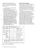
13. Reference-bit and change-bit values used to
determine the condition-code setting are
obtained by taking the logicalOR of the real
reference-bit and real change-bit values and the
virtual reference-bit and virtual change-bit
values, respectively. The swap-table word
previously fetched is updated in storage, with a
key of zero, by computing new values of three
bits. The backup reference-bit value and
backup change-bit value are updated by
logicallyORing those values and the values of
the real reference-bit and real change-bit
values, respectively. In addition, the virtual
reference bit of the swap-table word is set to
zero. The swap-table word contains two sets of
virtual and backup reference and change bits.
The value in bit position20 of the second
operand effective address determines which set
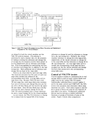
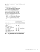
is used in this step. Figure10 shows the bit
position in the swap-table word used for each
bit (6).
The condition code is set, and execution of this
function ends with completion of the RESET
REFEREN CE BIT instruction.
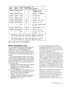
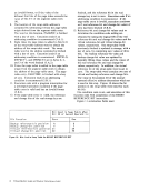
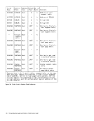
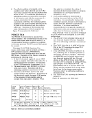
Figure 11 summarizes fields used.! I Bit
Bit Used in Swap Table When
Bit20 of Second Operand Is: Function Zero One
Backup reference-bit position 4 6
Backup change-bit position 5 7
Virtual reference-bit position 21 29
Virtual change-bit position 2230 Figure to. Bits Used in Swap Table for RESET REFERENCE BIT
16 Virtual-Machine Assist and Shadow-Table-Bypass Assist
leftmost four bits of the page index exceeds the
value of bits
(4 ).
8. The location of the swap-table address is
computed by subtracting 4 from the page-table
origin derived from the segment-table entry.
The word at this location, P AGSWP, is fetched
with a key of zero. Execution ends if an
addressing condition is encountered (S.A.l).
9. Eight times the page index is added to bits 8-31
of the swap-table-address word to obtain the
address of the swap-table word. The swap
table word at the address computed is fetched
with a key of zero. Execution ends if an
addressing condition is encountered. SWPFLG,
and 3 of the word fetched (S.A.2).
origin from the segment-table entry to obtain
the address of the page-table entry. The page
table entry,
of zero. Execution ends if an addressing
condition is encountered (S.B.l).
1 1. Execution ends with a program interruption for
a privileged-operation exception if the page
table entry is valid and has an invalid format
(S.B.2).
12.
and change bits of the real storage key are
fetched, and the reference bit in the real
storage key is set to zero. Execution ends if an
addressing condition is encountered. If the
page-table entry is invalid, execution continues
as if real reference-bit and change-bit values of
zero had been fetched (S.B.3).
13. Reference-bit and change-bit values used to
determine the condition-code setting are
obtained by taking the logical
reference-bit and real change-bit values and the
virtual reference-bit and virtual change-bit
values, respectively. The swap-table word
previously fetched is updated in storage, with a
key of zero, by computing new values of three
bits. The backup reference-bit value and
backup change-bit value are updated by
logically
the real reference-bit and real change-bit
values, respectively. In addition, the virtual
reference bit of the swap-table word is set to
zero. The swap-table word contains two sets of
virtual and backup reference and change bits.
The value in bit position
operand effective address determines which set
is used in this step. Figure
position in the swap-table word used for each
bit (6).
The condition code is set, and execution of this
function ends with completion of the RESET
REFEREN CE BIT instruction.
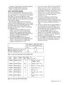
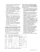
Figure 11 summarizes fields used.
Bit Used in Swap Table When
Bit
Backup reference-bit position 4 6
Backup change-bit position 5 7
Virtual reference-bit position 21 29
Virtual change-bit position 22
16 Virtual-Machine Assist and Shadow-Table-Bypass Assist