.
i
i
s
outines
n real
torage
routines
in real
storage
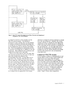
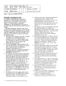
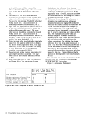
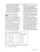
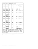
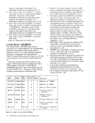
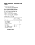
VM/370 dispatcher in
real storage
Figure 2. Real CPU Control Alternating between Direct Execution and Simulation of
Programs for Two Virtual Machines
are shared by both the virtual machine and the
performed in such a manner that, for the purposes
of testing or setting the reference and change bits
of storage keys by program control, there appear to
be two independent sets of reference and change
bits. This is accomplished by maintaining two sets
of reference and change bits in addition to the real
storage key. Both additional sets of reference and
change bits are kept in the swap table.
There
The word that precedes the first entry of each real
page table contains the address of the
corresponding swap table. A swap-table entry is
eight bytes long. Because
4K-byte page size, each swap-table entry contains
four sets of reference and change bits-two sets for
the lower 2K-byte block and two sets for the upper
2K-byte biock. Each 2K-byte block has a backup
reference bit and a backup change bit for the
bit and a virtual change bit for the virtual machine.
At any instant, the
bit is respectively the logical
reference or change bit and the reference or change
bit in the real storage key. Similarly, the virtual
machine reference or change bit is the logical
in the swap table and the reference or change bit in
the real storage key. If a real page-table entry is
invalid, the corresponding virtual page has been
swapped out, but the virtual reference and change
bits have been preserved in the corresponding
swap-table entry.
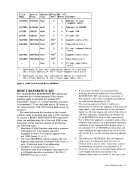
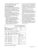
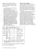
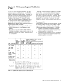
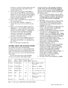
Control of
Control register 6 points to a parameter list in real
storage which is used to locate control blocks and
tables used by the various
Additionally, individual bits in control register 6
and in the assist control word (MICACF, the fifth
word in the parameter list) determine which assist
functions are active. Each assist requires a specific
bit or group of bits to be ones for any function of
that assist to be active. Furthermore, additional
bits are used to activate or inhibit individual
functions or groups of functions of some of the
assists. Figure 3 shows these assignments.
Assists for VM/370 3