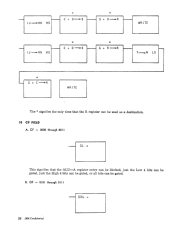
PK Field
PS Field
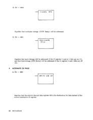
CK
0::
0011 (Wrap)
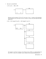
This is a
64I{
option. This condition allows the machine to test the wrap
latch and determine whether or not the I or U registers were wrapped.
If
I was wrapped, it blocks the X6 branch. If U was wrapped, it blocks the
X7 branch. (See example 8, page 25.)
CK
=
0100
(SHI)
This decode specifies the console switch values of H and I as the sources
for the K buss.
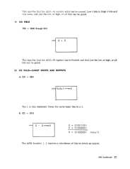
CK
=
0101 (AC
Force)
This decode specifies that if an address carry occurred in the previous
cycl~,
it forces the X register to zeros.
CK
=
01l0(0~
line)
This resets the 1050 to home loop.
CK
=
0111
(I
~
line)
This condition sets the 1050 to line loop.
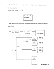
CK
=
1000
(I
~OE)
When this condition first occurs, it sets the odd/even latch to even. The sec-
ond time, it introduces an ALU check and resets the odd/even latch.
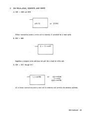
CK
=
1001 (ASCII)
This condition tests the ASCII latch, and if on, it forces the X6 bit to
O.
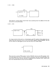
CK
=
1010 (INST)
This condition tests for interrupts; meanwhile, it creates a four-way
branch.
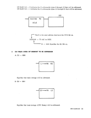
If
a MPX interrupt is indicated, the X6 and X7 bits remain the
same.
If
the interrupt is a SEL. 1, the X7 bit is forced to
o.
If
the interrupt is a
SEL. 2, the X6 bit is forced to
O. If
there is a TIMER or EXT. interrupt,
the X6 and X7 bits are both forced to O.
CK
=
1011
(O~
MC)
This condition resets the machine check register.
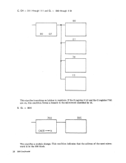
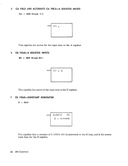
CK
=
1100 (Store Wrap)
This is a 64K option. It stores the value of the wrap latch into the buffer
wrap latch. (See example 8, page 25.)
CK = 1101
(O~
IPL)
This resets the load request, ALU check, odd/even, and SX diagnostic
latches.
CK
=
1110 (0
~
F)
This resets the external interrupt (F) 0 bit. And, if the L register 1 bit is
on, the F register 1 bit is reset. The same relationship exists for L2 through
7, and F2 through 7.
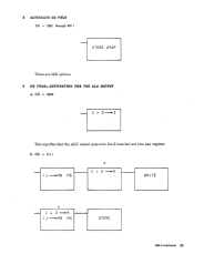
CK
=
IIII (I
~
FO)
This sets the external interrupt register (F) 0 to bit to a 1.
When CK is used at a position other than B, it must carry a parity bit.
When K goes to W, PK is odd parity. When K goes to the MN register, PK
is odd or even parity according to whether CNO is 0 or 1. When K goes to
I/O, PK indicates control and not parity. When CA is gated to W, a parity
bit is needed and PK is odd parity on the 5 bits consisting of 4 CA bits and
the AA bit.
This bit is called SAL parity and is odd parity on PA, CH, CL, CM, CU,
CA, CB, CK, and PK.
IBM Confidential
9
'j