Displaying Data
To display up to a full screen of data, code a CCW using the following assembler
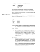
language instructions:DS OD DC ALl (CCWCODE) ,AL3(DATADDR) ,AL1 (FLAGS) ,AL1 (CTL) ,AL2(COUNT) where: CCWCODE is the command code X'19'.
DAT ADDR is the virtual storage address of the first byte of data to be displayed.
FLAGS
CTLCOUNT are standard CCW flags. The suppress-incorrect-Iength indicator, bit
34, must be set to a value of one. Set other bits as needed.
is a control byte defined as follows:
The high-order bit(0), if set on, enables the screen "MORE" sta
tus to be active before the displaying of data.
Bits 2-7 identify the line on the display screen where the display is
to start. A value of0 (B'xxOO 0000') corresponds to the first or
top line, a value of 1(B'xxOO 0001 ') corresponds to the second
line and so forth.
If the control byte contains the value X'FF',CP erases the display
station's screen. No new data is displayed.
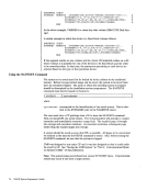
CCW's may be command chained to combine several operations in
oneDIAGNOSE. When CP builds the real CCW string, it will
data chain as many CCW's as possible to reduce the number of
realIIO operations. If the control byte contains a value of X'FE', CP will:
Not data chain this operation to any previous CCW in the real
CCW string.
Erase the entire screen.
Rewrite the attribute bytes for theCP screen format.
Reset the cursor to the beginning of the input area.
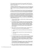
specifies the number of bytes of data to be displayed. The maximum
that can be specified for this command code is2032 bytes. The max
imum amount of data that can be displayed at one time depends upon
the3270 model of the display station:
A model 2 can display up to1760 bytes
A model 3 can display up to2400 bytes
A model 4 can display up to3280 bytes
A model 5 can display up to3300 bytes DIAGNOSE Instruction in a Virtual Machine 247
To display up to a full screen of data, code a CCW using the following assembler
language instructions:
DAT ADDR is the virtual storage address of the first byte of data to be displayed.
FLAGS
CTL
34, must be set to a value of one. Set other bits as needed.
is a control byte defined as follows:
The high-order bit
tus to be active before the displaying of data.
Bits 2-7 identify the line on the display screen where the display is
to start. A value of
top line, a value of 1
line and so forth.
If the control byte contains the value X'FF',
station's screen. No new data is displayed.
CCW's may be command chained to combine several operations in
one
data chain as many CCW's as possible to reduce the number of
real
Not data chain this operation to any previous CCW in the real
CCW string.
Erase the entire screen.
Rewrite the attribute bytes for the
Reset the cursor to the beginning of the input area.
specifies the number of bytes of data to be displayed. The maximum
that can be specified for this command code is
imum amount of data that can be displayed at one time depends upon
the
A model 2 can display up to
A model 3 can display up to
A model 4 can display up to
A model 5 can display up to