IBM 2821 Control Unit Component Description
IBM 3211 Printer
IBM 3216 Interchangeable Train Cartridge
IBM 3811 Printer ControlUnit Component Description and Operator's Guide
IBM 3289 Line Printer Model 4 and Component Description
IBM 3262 Printers I and II Component Description.
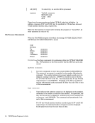
The following table indicates in what module the images for each printer should be
coded:
Data Module
DMKFCBDMKUCS DMKUCC
DMKPIA
DMKPIB
DMKUCB
Printer
All 3211 type printersUCS image for the 1403 printer UCS image for the 3203 printer UCS image for the 3289E printer UCS image for the 3262-1/11 printer UCS image for the 3211 printer
For further information refer to the Component Description of the printer for
which the image is being coded.
If you find that the supplied buffer images do not meet your needs, you can alter a
buffer image or create a new buffer image. Be careful not to violate theVM/SP coding conventions if you add a new buffer image; buffer images must not cross
page boundaries.
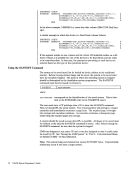
Adding New Print Buffer Images
In order to add a new print buffer image toVM/SP, you must:
1. Provide a buffer image name and 12 byte header for the buffer load.
2. Provide the exact image of the print chain.
3. Provide a means to print the buffer image ifVER is specified on the LOADBUF command.
4. Reload the changed CP modules.
Macros are available that make the process of adding buffer images relatively easy
and should be used to avoid errors.UCS Buffer Images for the 1403 Printer
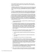
The Universal CharacterSet (UCS) buffer contains up to 240 characters and sup
ports the1403 printer. To add a new UCS buffer image, first code the UCS macro. This creates a 12-byte header for the buffer load that is used by CPo The
format of theUCS macro is:
Print Buffers and Forms Control 283
IBM 3211 Printer
IBM 3216 Interchangeable Train Cartridge
IBM 3811 Printer Control
IBM 3289 Line Printer Model 4 and Component Description
IBM 3262 Printers I and II Component Description.
The following table indicates in what module the images for each printer should be
coded:
Data Module
DMKFCB
DMKPIA
DMKPIB
DMKUCB
Printer
All 3211 type printers
For further information refer to the Component Description of the printer for
which the image is being coded.
If you find that the supplied buffer images do not meet your needs, you can alter a
buffer image or create a new buffer image. Be careful not to violate the
page boundaries.
Adding New Print Buffer Images
In order to add a new print buffer image to
1. Provide a buffer image name and 12 byte header for the buffer load.
2. Provide the exact image of the print chain.
3. Provide a means to print the buffer image if
4. Reload the changed CP modules.
Macros are available that make the process of adding buffer images relatively easy
and should be used to avoid errors.
The Universal Character
ports the
format of the
Print Buffers and Forms Control 283