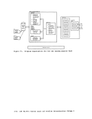
Figure 1.
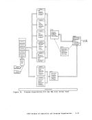
FiJure 2.
Figure 3.Figure 4. Fi;Iure 5.
Figure 6.
Figu:r:e 7.Figure 8.
I'igure 9.
Figure10. Figure 11. Figure 12.
Figure 13.
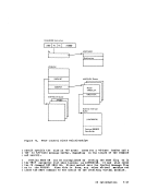
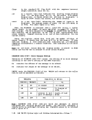
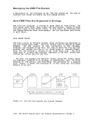
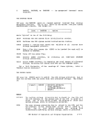
Figure 14.CftS File System ••••••••••••• 2-6
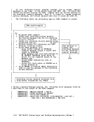
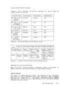
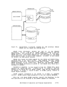
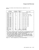
DevicesSupporte1 by a virtual 5achine •••••••••••• 2-13 CftS Storage ftap •••••••••••• 2-16 CftS Request; processing ••••••••••••••••• 2-30 PSi Fields when :alled Routine Starts ••••••••••••• 2-31
RegisterConte&ts when :alled
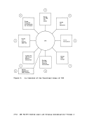
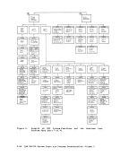
Routine Starts••••••••••••• 2-31 Simulated os Supervisor Calls ••••••••••• __ .========2-31 An Overview of the Functional
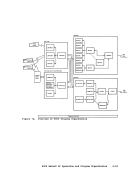
AreasCKS ••••••••••••••• 2-52
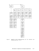
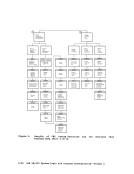
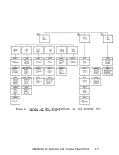
Details ofCftS Systea Functions and the Routines that
PerformThem ••••••••••••••• 2-53 PSi Fields when Callea Routine is Started ••••••••• 2-69
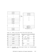
Register Contents when:alled Routine is Started ••••••••• 2-10 How CMS File Records are
Chained Togehter••••••••••• 2-86
Format of a FileStatus Block; Format of a rile Status rable •••••••••••••••••••••• 2-86
For.at of the First Chain
Link and Nth••• 2-89
Figure 16.
Figure 17.Figure 18. Figure 19. FIGURES Recoras and Variable-Length Re=oris in Files ••••••••••• 2-B9
structure of theMaster File Directort ••••••••••••• 2-92
DiskStorage Allocation Using the QMSK Data Block •••••••• 2-92
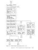
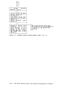
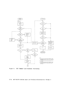
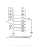
Flow of Control forUnit Recora I/O processing •••••• 2-94
Relationships in storage
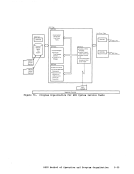
between theCMS Interface CMSAMS ana CHSVSAM DCSSs •••••••••••••••••••• 20. The Relationships in storage between the User Program and the ana CMSVSAft DCSSs ••••••••• 2-111
Figure 21. Relationship in storage
between theUser Program, the os Simulation and
Interface Routines, and theCMSDOS ana CMSVSAft DCSSs •• 2-118 figure 22. OS Functions that CMS Simulates ••••••••••••••••• 2-123
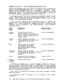
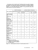
Figure 23. Devices Supported by aVirtual Machine ••••••••••• 2-239
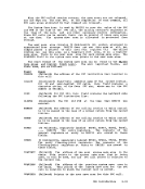
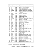
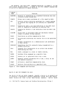
Figure24. CBS Abend Codes ••••••••••• 2-243 Contents vii
FiJure 2.
Figure 3.
Figure 6.
Figu:r:e 7.
I'igure 9.
Figure
Figure 13.
Figure 14.
Devices
Register
Routine Starts
Areas
Details of
Perform
Register Contents when
Chained Togehter
Format of a File
For.at of the First Chain
Link and Nth
Figure 16.
Figure 17.
structure of the
Disk
Flow of Control for
Relationships in storage
between the
Figure 21. Relationship in storage
between the
Interface Routines, and the
Figure 23. Devices Supported by a
Figure