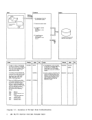
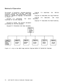
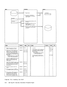
Figure 1-1.
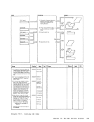
Figure 1-2.
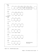
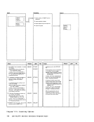
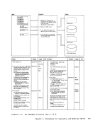
Figure 1-3.
Figure 1-4.
Figure 1-5.
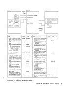
Figure 2-1.
Figure 2-2.
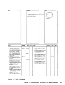
Figure 2-3.
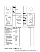
Key toVirtual Disk
InitializationMethod of
Operation Diagrams•••••••• •• 5 Virtual Disk Initialization Program Label Directory ••• IBCDASDI Track Zero ••••••••• 12
unit Control Block•••• ' •••••• 13 IBCDASDI Messages ••••••••••• 14
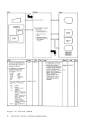
Key to InteractiveProblem Control System Method of
Operation Diagrams•••••••••• 20 Interactive Problem Control System (IPCS) Label
Directory•••••••••• •• _ ••••• 48 VMFDUMP Shared Constant
Area•••••••••••••••••••••••• S4 Figure 2-4. VMFDUMP and PROB Internal
Figure 2-5.
Figure 2-6.
Figure 3-1.
Figure 3-2.
Figure 3-3.
Figure 3-4.
Figure 3-5.
Figure 3-6.
Figure 3-7.
Figure 3-8.
Figure 3-9.
Figure3-10. Figure 3-11.
Figure 3-12.
Figure 3-13.
Figure 3-14.
Figure 3-15.
Figure 3-16.
Figure 3-17.
Figure 3-18.
Figure 4-1.
Figure 4-2.
Figure 4-3.
Figure 5-1.
Figure 5-2.
Figure 5-3,.
Figure 5-4.
Figure 5-5.
DataArea_ ••••••••••••••••• Symptom Su.mary Control
Record Format.,••• , ••••• , •••••• 58
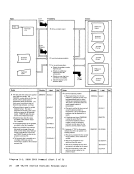
InteractiveProblem Control System Messages ••••••••••••• 60 Key to the Format/Allocate Program Method of Operation
Diagrams•••••••••••••••••••• 65
The Format/AllocateProgram Label Directory •••••• •••••• 70 Record 0 Format ••••• ••••••• 71
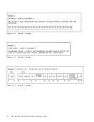
Record 1 For.at•••••••• •••• 72
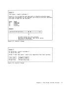
Record 2 Format••••••••••••• 72
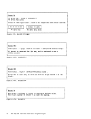
Record 3 Format••••••••••••• 72
Record 4 Format••••••••••••• 73
Record 5 Format••••••••••••• 73
Record 6 Format••••••••••••• 74
Record F3••• ' •••••••••••••••• 74
Record F4••••••••••••• : ••••• 74
Record 4•••••••••••••••••••• 74
2314/2319 Record Layout••••• 75 3330 Series Record Layout ••• 76 2305 Models 1 and 2 Record
Layout•••••••••••••••••••••• 77 3340 Record Layout •••••••••• 78 3350 Record Layout •••••••••• 79 The Format/Allocate Program Messages •••••••••••••••••••• 80 Key to the Directory Program Method of Operation
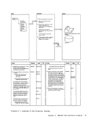
Diagrams•••••••••••••••••••• 82
The DirectoryProgram Label
Directory••••••• ••• •••••• 89
The DirectoryProgram Messages •••••••• __ •••••••••• 92
Key to theDASD Dump Restore Program Method of Operation
Diagrams••••••• •••• __ •••• 94
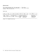
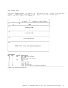
TheDASD Dump Restore Program Label Directory •••• 103 Cylinder Header Record ••••• 106 Track Header Record •••••••• 107 lOB (Input/Output Block)
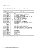
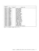
For.at••••••••••••••••••••• 108 Figure 5-6. The DASD Du.p Restore
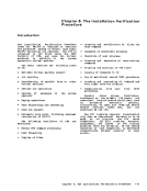
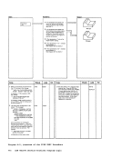
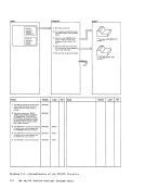
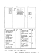
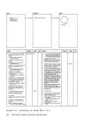
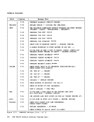
program Messages••••••••••• 110 Figure 6-1. Key to the Installation Verification procedure Method of Operation Diagrams ••••••••••••••••••• 114
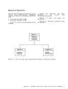
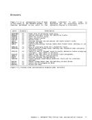
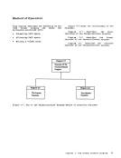
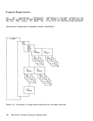
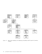
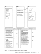
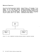
Figure 6-2.Structure of Installation Verification procedure
Routines••••••••••••••••••• 120 Figure 6-3. Installation Verification Procedure Tests •••••••••••• 121
Figure 6-4. InstallationVerification Procedure Label Directory, •• 122
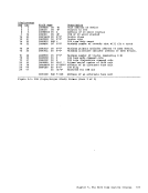
Figure 6-5. The Installation
Figure 7-1.
Figure 7-2.
Figure 7-3.
Figure 7-4.
Figure 7-5.
Figure 7-6.
Figure 7-7.
Figure 7-8.
Figure 7-9.
Figure7-10. Figure 7-11.
Figure 8-1.
Figure 8-2.
Figure 9-1.
Figure 9-2.
Figure 9-3.
Figure 9-4.
Figure 9-5.
Figure 9-6.
Figure 9-7.Verification procedure
Messages••••••••••••••••••• 123
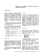
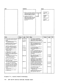
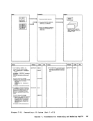
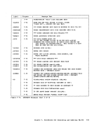
Key to theProcedures for
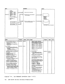
Generating andUpdating VM/370 Method of Cperation
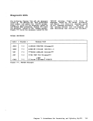
Diagra.s••••••••••••••••••• 130 GENERATE Introductory
Message•••••••••••••••••••• 146
Label Directory for
AssemtlerUpdate Procedure.151 The VMFLOAD program Label
Directory••••••••••• _ •••••• 153
TheVMFMAC Erocedure Label
Directory•••••••••••••••••• 153
TheGENERATE procedure
Label Directory•••••••••••• 154 VMFASM Messages •••••••••••• 155 DMSUPD Messages •••••••••••• 156 VMFLOAD Messages ••••••••••• 157 VMFMAC Messages •••••••••••• 157 GENERATE Messages •••••••••• 158
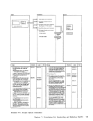
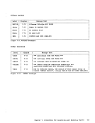
TheStarter system (DMKSSP) Label Directory •••••••••••• 167 The Starter system (DMKSSP) Messages ••••••••••••••••••• 168
Key to the3704/3705 Service Programs Method of
Cperation Diagrams••••••••• 170 Module Directory for the 3704/3705 Command
Processors••••••••••••••••• 185
TheNCPDUMP Command Processor (tMKRNt) Label
Directory•••••••••••••••••• 185 The ASM3705 Command Processor (tMSARJ) Label
Directory•••••••••••••••••• 186
TheASM3705 Command Processor (DMSARX) Label
Directory•••••••••••.••••• ' •• 186
TheGEB3705 Command
Processor(tMSGRJ) Label
Directory•••••••••••••••• , •• 187 The LKED Co.mand Processor (DMSLKD) Label tirectory ••• 188
viii IBMVM/370 Service Routines Program Logic
Figure 1-2.
Figure 1-3.
Figure 1-4.
Figure 1-5.
Figure 2-1.
Figure 2-2.
Figure 2-3.
Key to
Initialization
Operation Diagrams
unit Control Block
Key to Interactive
Operation Diagrams
Directory
Area
Figure 2-5.
Figure 2-6.
Figure 3-1.
Figure 3-2.
Figure 3-3.
Figure 3-4.
Figure 3-5.
Figure 3-6.
Figure 3-7.
Figure 3-8.
Figure 3-9.
Figure
Figure 3-12.
Figure 3-13.
Figure 3-14.
Figure 3-15.
Figure 3-16.
Figure 3-17.
Figure 3-18.
Figure 4-1.
Figure 4-2.
Figure 4-3.
Figure 5-1.
Figure 5-2.
Figure 5-3,.
Figure 5-4.
Figure 5-5.
Data
Record Format.,
Interactive
Diagrams
The Format/Allocate
Record 1 For.at
Record 2 Format
Record 3 Format
Record 4 Format
Record 5 Format
Record 6 Format
Record F3
Record F4
Record 4
2314/2319 Record Layout
Layout
Diagrams
The Directory
Directory
The Directory
Key to the
Diagrams
The
For.at
program Messages
Figure 6-2.
Routines
Figure 6-4. Installation
Figure 6-5. The Installation
Figure 7-1.
Figure 7-2.
Figure 7-3.
Figure 7-4.
Figure 7-5.
Figure 7-6.
Figure 7-7.
Figure 7-8.
Figure 7-9.
Figure
Figure 8-1.
Figure 8-2.
Figure 9-1.
Figure 9-2.
Figure 9-3.
Figure 9-4.
Figure 9-5.
Figure 9-6.
Figure 9-7.
Messages
Key to the
Generating and
Diagra.s
Message
Label Directory for
Assemtler
Directory
The
Directory
The
Label Directory
The
Key to the
Cperation Diagrams
Processors
The
Directory
Directory
The
Directory
The
Processor
Directory
viii IBM