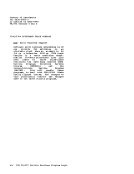
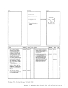
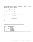
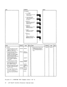
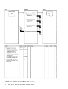
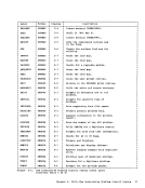
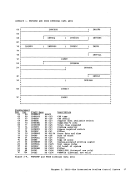
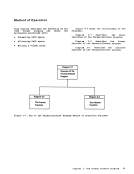
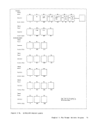
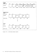
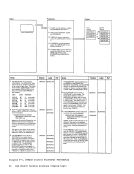
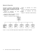
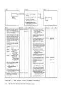
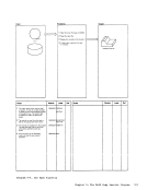
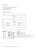
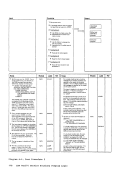
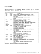
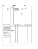
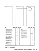
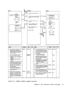
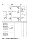
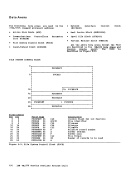
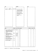
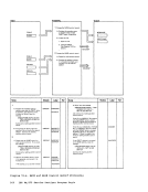
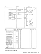
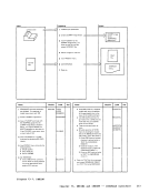
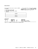
Method of Operation
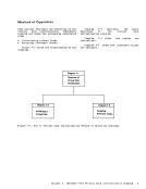
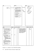
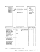
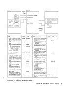
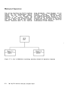
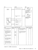
The method of operation diagrams describe
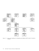
the major functions of the DDR(DASD Dump Restore) program. The relationship of the method of operation diagrams is described
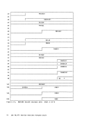
in Figure 5-1.Diagram 5-1 describes
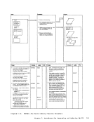
functions of the DDRprogram. the major Diagram 5-2 shows the control statement
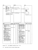
Frocessing for the DDR•• Diagram 5-3 describes the
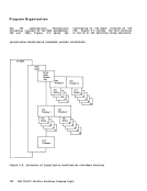
Diagram5-2 Diagram 5-3 DDR Program Control The Dump
Statement Function
Processing
Diagram 5-4
The Restore
Function
Diagram5-1 Overview of the DDR
ProgramDiagram function.
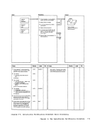
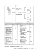
5-4cescribes the Restore Diagram 5-5 describes the copy function.
Diagram
function.
5-6 describes thePrint Diagram 5-7 describes the Type function.
Diagram5-5 Diagram 5-6 Diagram 5-7 The Copy The Print The TVpe
Function Function Function
Figure 5-1. Key to theDASD Dump Restore Program Method of Operation Diagrams 94 IBM VM/370 Service Routines Program Logic
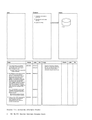
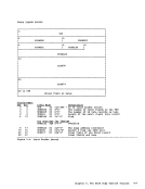
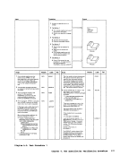
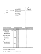
The method of operation diagrams describe
the major functions of the DDR
in Figure 5-1.
functions of the DDR
Frocessing for the DDR
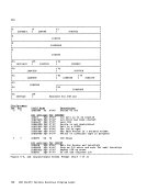
Diagram
Statement Function
Processing
Diagram 5-4
The Restore
Function
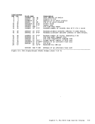
Diagram
Program
5-4
Diagram
function.
5-6 describes the
Diagram
Function Function Function
Figure 5-1. Key to the