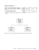
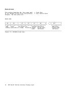
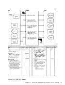
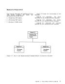
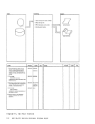
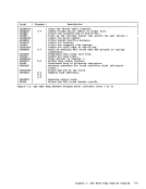
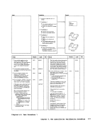
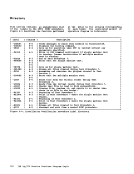
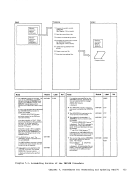
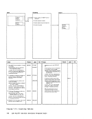
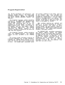
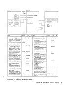
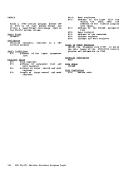
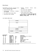
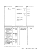
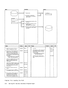
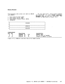
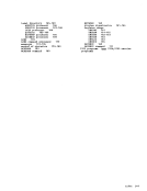
Method of Operation
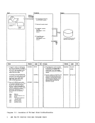
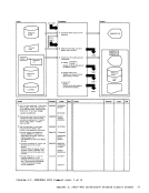
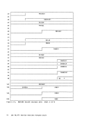
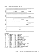
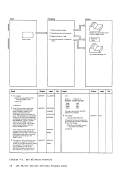
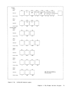
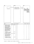
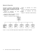
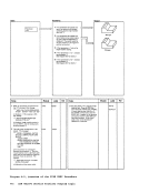
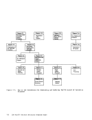
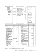
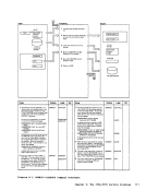
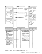
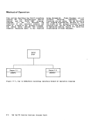
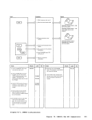
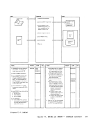
This section describes the execution of thetwo EXEC procedures of the IVP (Installation Verification Procedure) • Figure 6-1 shows the relationship of the
diagra.s.
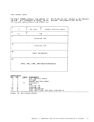
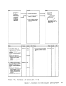
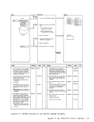
Diagrall 6-1 describes the highest levelEXEC procedure, IVP.
Diagram 6-1
TheIVP EXEC Procedure I Diagram 6-3
Test
Procedure 1
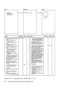
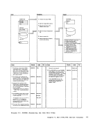
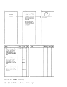
Diagrall 6-2 describes themajor functions of the nested EXEC procedure IVPX. tiagrall 6-3 describes test Diagram 6-4 describes test
tiagrall 6-5
processing.
describes
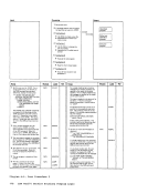
Diagram 6-2
Overview of theIVPX EXEC Procedure I Diagram 6-4 Diagram 6-5 Installation Test
Verification
Procedure 2
Procedure
Error
Processing
procedure 1.
procedure 2.
the error
Figure 6-1. Key to the InstallationVerification Procedure 8ethod of Operation Diagralls
114IB8 V8/370 Service Routines Progra. Logic
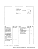
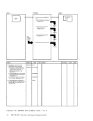
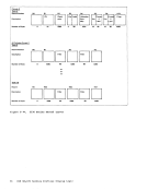
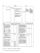
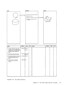
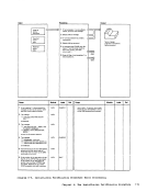
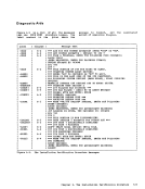
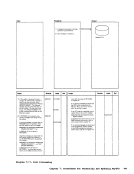
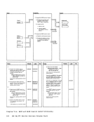
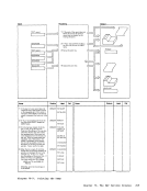
This section describes the execution of the
diagra.s.
Diagrall 6-1 describes the highest level
Diagram 6-1
The
Test
Procedure 1
Diagrall 6-2 describes the
tiagrall 6-5
processing.
describes
Diagram 6-2
Overview of the
Verification
Procedure 2
Procedure
Error
Processing
procedure 1.
procedure 2.
the error
Figure 6-1. Key to the Installation
114