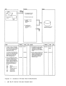
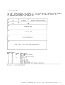
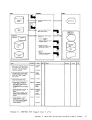
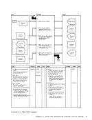
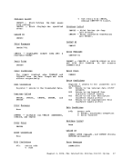
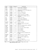
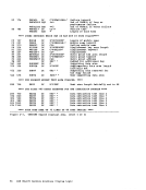
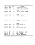
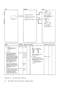
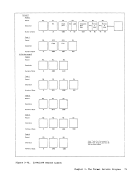
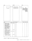
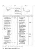
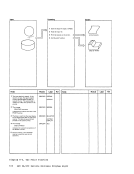
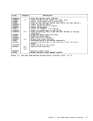
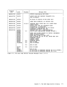
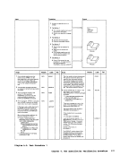
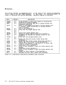
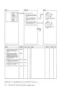
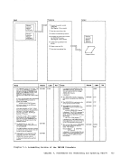
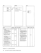
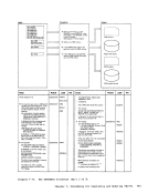
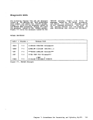
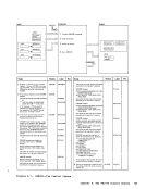
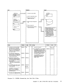
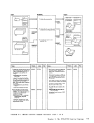
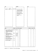
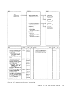
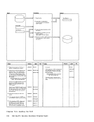
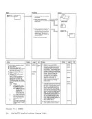
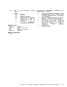
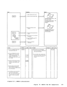
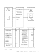
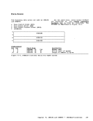
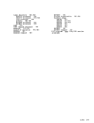
Processing ImaQe of failing command --,-----> If test procedure 1 running discon nected, punch aii the messages.
Expected
return
code
Received
return
code
Notes
1
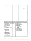
2If test machine 1 is disconnected the
messages are sent to thepunch, rather
than the virtual machine console.
The message- _ ............. ,,"'" ___ I I,", IV .... r-AILUrll: nA;)UvvUn RED ***
is displayed.
3 The messages
***IVP HAS FAI LED -REPLY NO TO ABO RT M ESSAG E *** SIGNAL ATTN AND ENTER: BEGIN are sent to the system operator.
4 The messages
*** COMMAND: xxxxxxxx
*** EXPECTED RETURNCODE xxx
***RECEIVED RETURN CODE xxx
are displayed.
5 Control returns to the nextlevel EXEC
procedure and the return code of 1
forces thatlevel to return to the CMS
commandenv;·onrr.ent. Is I If the number of the test section is less
than6, all the IVPTST files are erased. If the number of the test section is
greater than5, all the IVPTST2 files
are erased. Because this is a nested
EXECprocedure, exit with a nonzero
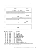
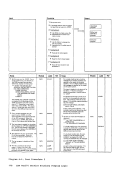
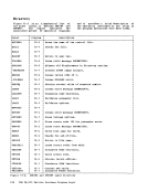
ModuleIVPX IVPX IVPX IVPX IVPX IVPX 2 Display failure messages.
3If running standard test, display
instructions.
4 Displayfailing command.
5If command was ERASE with file type of * and the single machine
test is notrunning, exit with
return code 1.Is E
· I CMS
raseall files of test procedure 1 or
test procedure 2.Label Ref Notes
-CHECK1 return code. A nonzero return code
forces the nextlevel EXEC to return
to the CMS command environment.I II -CHECK2 -QUIT failure message
[operator instructions)
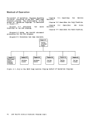
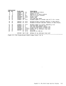
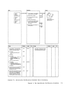
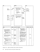
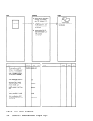
failing commandModule Label Diagraa 6-5. Installation Verification Procedure Error Processing
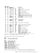
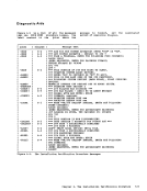
Ref
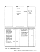
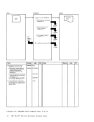
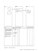
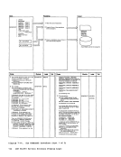
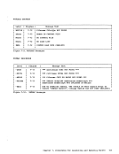
Chapter 6. The Installation VerificatioDProcedure 119
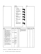
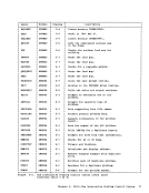
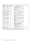
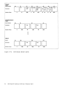
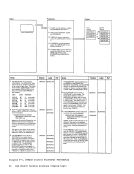
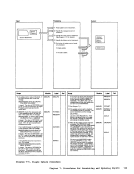
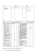
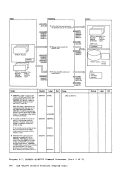
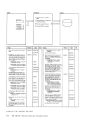
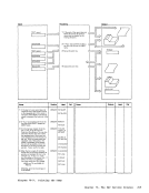
Expected
return
code
Received
return
code
Notes
1
2
messages are sent to the
than the virtual machine console.
The message
is displayed.
3 The messages
***
4 The messages
*** COMMAND: xxxxxxxx
*** EXPECTED RETURN
***
are displayed.
5 Control returns to the next
procedure and the return code of 1
forces that
command
than
greater than
are erased. Because this is a nested
EXEC
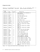
Module
3
instructions.
4 Display
5
test is not
return code 1.
·
rase
test procedure 2.
-CHECK1 return code. A nonzero return code
forces the next
to the CMS command environment.
[operator instructions)
failing command
Ref
Chapter 6. The Installation VerificatioD