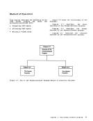
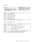
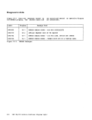
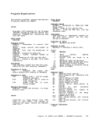
Method of Operation
This section
procedures ferV8/370: describes
genera ting• Update procedure • Nucleus loading facility
the following
and updating• The MACLIB generation facility
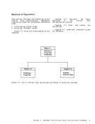
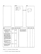
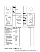
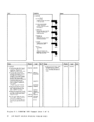
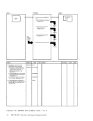
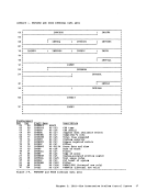
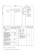
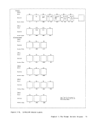
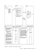
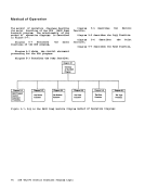
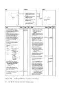
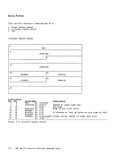
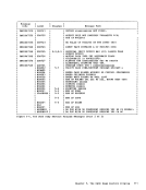
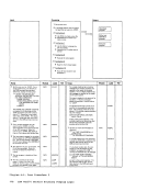
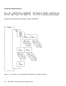
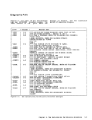
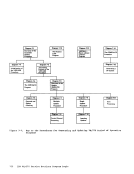
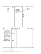
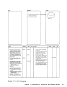
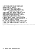
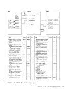
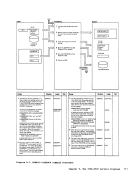
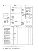
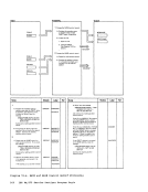
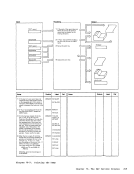
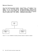
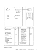
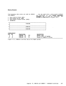
Figure 7-1 shows the relationship of the
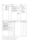
diagrams.Diagra. 7-1 shows the :ajor functions of
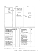
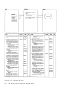
theV8FAS8 procedure. Diagram 7-2 shows the initialization of
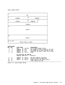
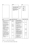
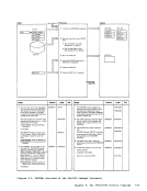
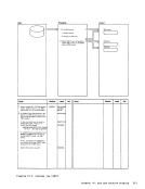
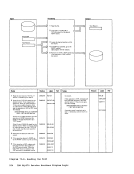
theVMFASM procedure. Diagram 7-3 describes the assembling portion of the VMFASM procedure. Diagram program. 7-4 describes the VMFDATE Diagraa 7-5 describes the major functions of the DMSUPD (update) progra=. Diagram 7-6 describes the operand and
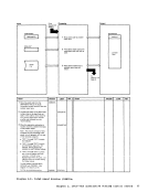
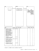
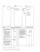
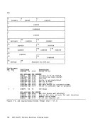
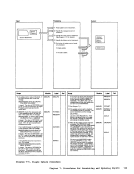
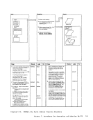
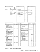
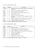
option checking for theUpdate program. tiagram 7-7 describes the multiple level
update procedure.tiagram 7-8 describes the processing cf
control records for theUpdate program. Diagram 7-9 describes the single level
update procedure.
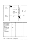
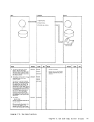
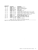
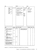
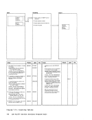
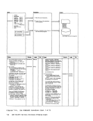
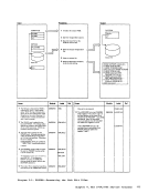
Diagram7-10 shows how inserting is
done.Diagram 7-11 describes the exit procedure for the Update program. Diagram 7-12 describes the .odule load
program.
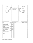
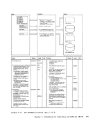
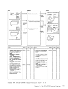
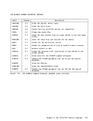
Diagram 7-13 describes the Frocedure
that builds the8ACLIB. Diagram 7-14 describes the major functions of the GENERATE procedure. Diagra= 7-15 describes the CP pcrtion of
theGENERATE procedure.
Chapter7. Procedures for Generating and Updating V!/370 129
This section
procedures fer
genera ting
the following
and updating
Figure 7-1 shows the relationship of the
diagrams.
the
the
option checking for the
update procedure.
control records for the
update procedure.
Diagram
done.
program.
Diagram 7-13 describes the Frocedure
that builds the
the
Chapter