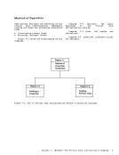
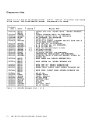
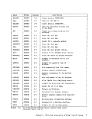
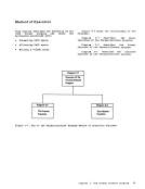
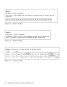
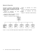
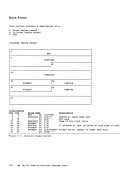
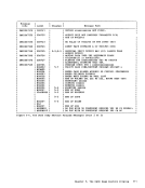
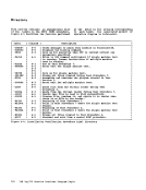
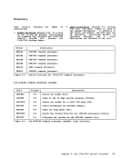
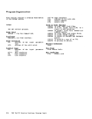
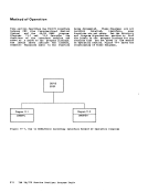
Method of Operation
This section describes Interactive problem
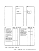
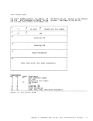
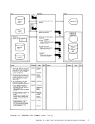
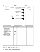
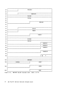
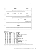
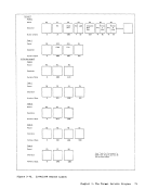
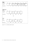
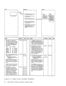
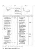
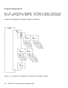
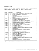
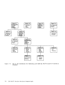
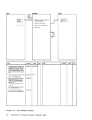
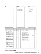
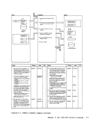
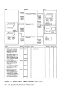
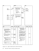
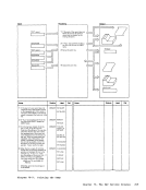
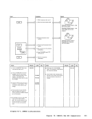
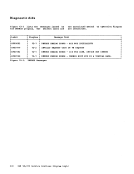
ControlSystem (IPCSj. Diagrams describe the five IPCS functions. Figure 2-1 shows
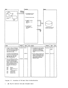
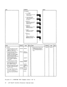
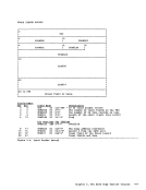
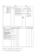
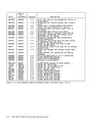
the relationship of these diagrams.Diagram 2-1 shows how the DUMPSCAN command and its subcommands enable the user
to interactively examine aCMS dump file
createdby VM/370. Diagram 2-2 shows how updates the status of
symptom summary file.
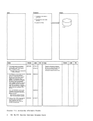
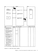
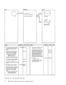
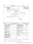
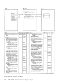
thePRE problems command in the Diagram 2-3 shows how the PROB command
createsproblem reports and adds
information to existing problem reports.
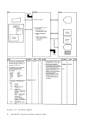
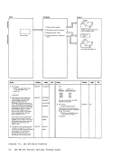
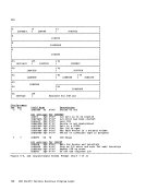
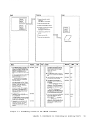
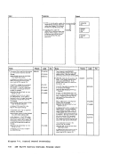
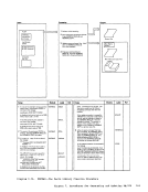
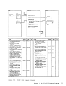
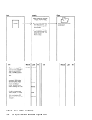
Diagram 2-4 shows how the
lists the current status
problem.
STAT command
of a given
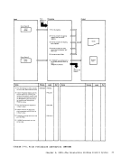
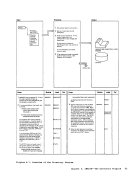
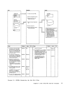
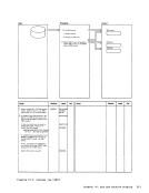
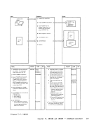
Diagram 2-5 shows an overview of how theVMFDUMP command creates a problem report by
extracting pertinent datafrom a VM/370 CP abend dump.
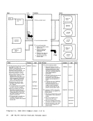
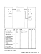
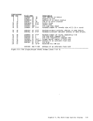
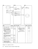
Diagram 2-6 shows how the nucleus load
map is compressed.
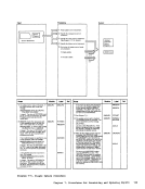
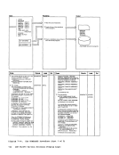
Diagram 2-7 shows how aprogram check is
handled.
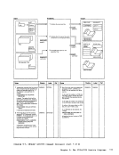
Diagram 2-8 shows how
handled.. a ceded abend is
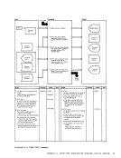
Diagram 2-9 shows how
initiated dump is handled.
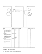
an operatorDiagram 2-10 shows how the preliminary
information is printed.Diagram 2-11 shows how the
blocks are formatted and printed.
contrel
Diagram 2-12 showshow the storage
protection keys and dump file areprinted. Chapter 2* IPCS--The Interactive prcblem centrel System 19
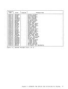
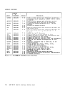
This section describes Interactive problem
Control
the relationship of these diagrams.
to interactively examine a
created
symptom summary file.
the
creates
information to existing problem reports.
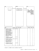
Diagram 2-4 shows how the
lists the current status
problem.
STAT command
of a given
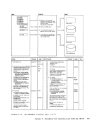
Diagram 2-5 shows an overview of how the
extracting pertinent data
Diagram 2-6 shows how the nucleus load
map is compressed.
Diagram 2-7 shows how a
handled.
Diagram 2-8 shows how
handled
Diagram 2-9 shows how
initiated dump is handled.
an operator
information is printed.
blocks are formatted and printed.
contrel
Diagram 2-12 shows
protection keys and dump file are