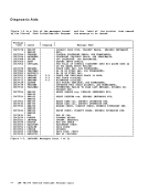
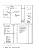
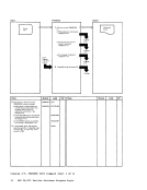
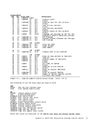
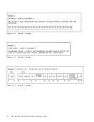
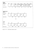
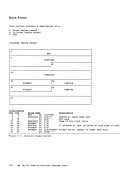
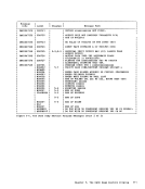
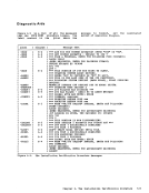
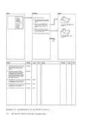
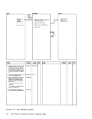
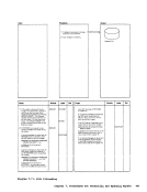
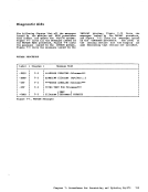
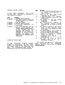
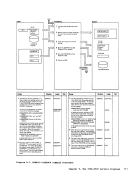
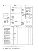
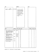
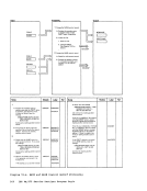
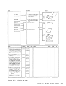
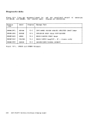
1 Examine the wait bit in the current
waiting when the operator depressed
the SYSTEM RESTART key. Move
wait code.
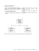
the
tion
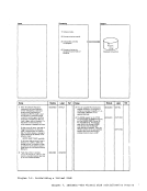
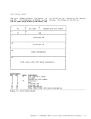
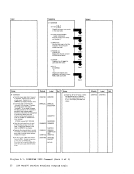
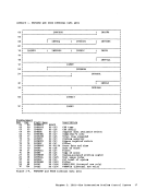
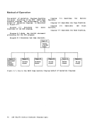
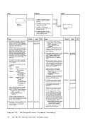
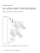
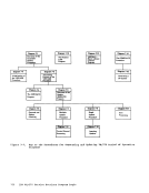
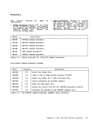
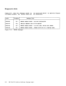
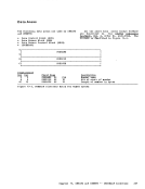
Diagram
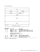
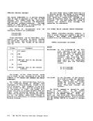
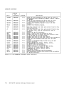
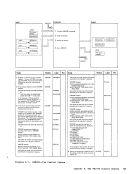
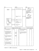
2 Locate the
all operator initiated
them to the
routine (Diagram
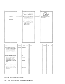
From Processing
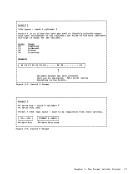
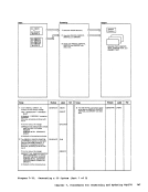
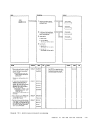
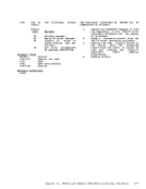
Diagram 2-5 _--------------..,
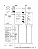
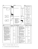
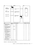
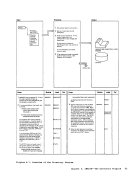
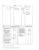
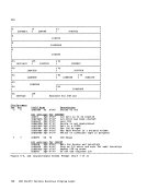
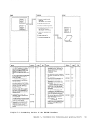
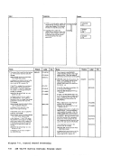
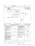
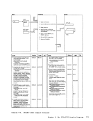
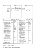
(Step 3)
prompt the user for this
information if the reason for the
dump cannot be determined
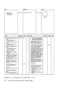
(Diagram
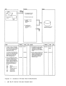
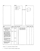
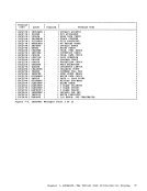
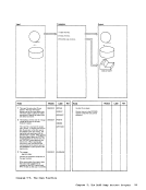
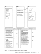
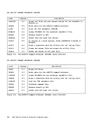
2 Locate the
entries, move them to the
EXTLEAV
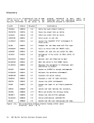
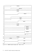
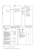
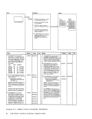
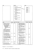
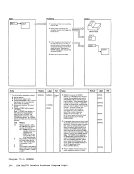
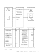
Diagram 2-9. Operator Initiated Routine
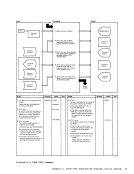
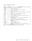
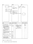
To
Diagram 2-5
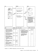
(Step 4)
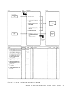
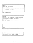
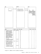
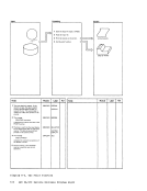
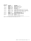
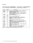
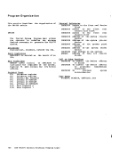
Output
TEXT2
TEXT3
TEXT4
Module