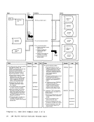
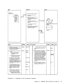
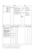
Figure 9-12.
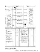
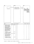
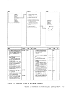
Figure 9-13.
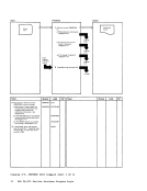
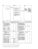
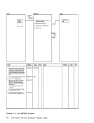
Figure 9-14.
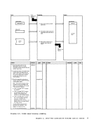
Figure
Processor
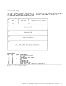
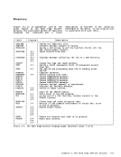
Directory
File
(FSCB):
Processor
Messages
The
Processor
Messages
The
The LKED Command
Processor
Messages
The
Processor
Messages
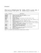
Diagrams
The
Directory
Figure 11-2.
Directory
Figure 11-3.
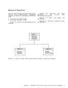
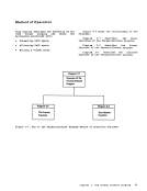
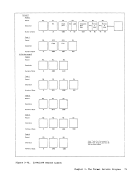
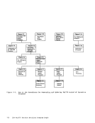
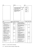
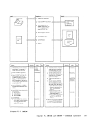
Figure 12-1. Key to the
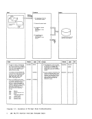
Figure 12-3.
Directory
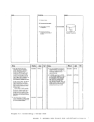
Figure 13-3.
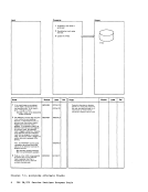
Figure 13-4.
contents ix