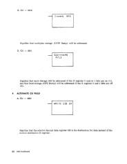
Alternate CK Field . . . . . . . . . . .
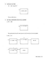
CD Field-Destination for the ALU Output
CF Field ............ .
CG Field ............ .
CC Field-Carry Inputs and Outputs
CS Field-Status
APPENDIX . ....
iv
IBM Confidential
25
25
. .. 26
27
27
29
31

Introduction
This manual was written to provide an understanding of the microprogramming language for
the people involved with creating or interpreting microprograms on the IBM System 360-Model 30.
]VIicroprogramming provides the control for most of the functions performed in the IBM System
360-Model 30. These functions consist of memory control, Arithmetic and Logic Unit Controls
(ALU), hardware register input and output controls, machine status controls, Read Only Storage
(ROS), sequencing controls and some I/O controls.
The microprogramming instructions are explained individually to simplify the complexity of
the microprogramming language. Each instruction has a description of the control field bit struc-
ture, branching conditions, hardware registers and latches, and buss and tag lines involved. Charts
are also provided for timings, microword formats, data-flow and local storage layout to clarify the
microprogramming functions.
Model 30 Machine Control Specifications
The Read Only Storage (ROS) must provide control for most of the functions performed in the
Model 30. These functions, to repeat, consist of memory control, ALU (Arithmetic and Logic Unit)
controls, hardware register input and output controls, machine status controls, ROS sequencing
control and some I/O control.
The Data Flow Chart for the Model 30 is shown in the Appendix. The breakdown of the ROS
output, as punched in a bit card, can also be found in the Appendix. A GEOG address is the loca-
tion of the ROS word on the microprogramming flow diagram. The HEX address is the location of
the word in the ROS. The output is described in columns 11 through 72 (62 bits) of the CCROS
Document Card.
The ROS output is divided into subfields called control fields. Some control fields may be de-
coded and used directly from the Sense Amplifier Latches (SAL). Some control fields require a con-
trol register to hold the ROS output information until it is used.
Control Field Description
CN-6 Bits
PN-I Bit
PA-I Bit
CH-4 Bits
CL-4 Bits
CM-3 Bits
.#CU-2 Bits
#CA-4 Bits
AA-I Bit
CB-2 Bits
#CK-4 Btis
AK-I Bit
PK-I Bit
PS-I Bit
Next ROS address
Odd parity on CN
Odd parity on address of ROS word
ROS address branching
Address register/read write select
Main storage or local storage data destination
Input source for A buss and A register
Alternate CA decoder bit
Input source for B buss and B register
Constant generator
Alternate CK decoder bit
Parity for CK field
Odd parity for SAL's
IBM Confidential
1\
Previous Page Next Page