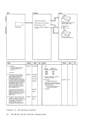
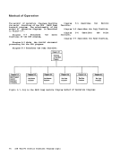
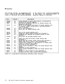
Diagram 1-1.
Diagram 1-2.
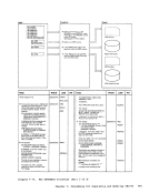
Diagram 1-3.
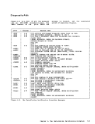
Diagram 2-1.
Diagram 2-2.
Diagram 2-3.
Diagram 2-4.
Diagram 2-5.
Diagram 2-6.
Diagram 2-7.
Diagram 2-8.
Diagram 2-9.
Diagram2-10. Diagram 2-11.
Diagram 2-12.
Diagram 3-1.
Diagram 3-2.
Diagram 3-3.
Diagra. 4-1.
Diagram 4-2.
Diagram 4-3.
Diagram 4-4.
Diagram 4-5.
Diagram 5-1 ..
Diagram 5-2.
Diagram 5-3.
Diagram 5-4.
Diagram 5-5.
Diagram 5-6.
Diagram 5-7.
Diagram 6-1.
Diagram 6-2.
Diagram 6-3.
Diagram 6-4.
Diagram 6-5.
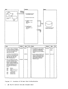
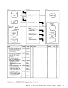
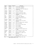
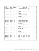
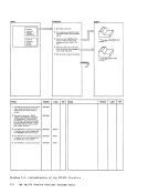
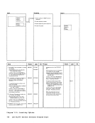
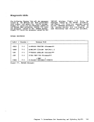
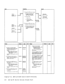
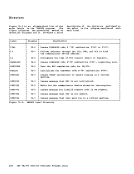
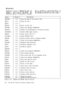
Overview ofVirtual Disk
Initialization•••••••••••••• 6
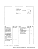
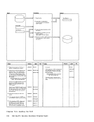
Initializing aVirtual Disk •••••••••••••••••••••••• ? Assigning Alternate Tracks •• 8 DUMPSCAN IPCS Command •••••• 21 PRB IPCS Co.mand ••••••••••• 24 PROB IPCS Command •••••••••• 25 STAT IPCS Command •••••••••• 27 VMFDUMP IPCS Command ••••••• 28 Compress the Nucleus
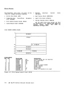
Load Map••••••••••••••••••• 31
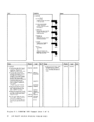
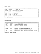
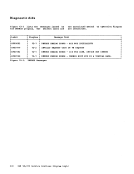
ProgramCheck Routine (DMMPRG) .................... 32 Coded Abend Routine (DMMCPA) ••••••••••••••••••• 33
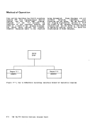
Operator Initiated Routine(DMMINI) ••••••••••••••••••• 34 Print preliminary
Information(DMMEDM) ••••••• 35
Format andPrint Control Blocks (DMMEDM) •••••••••••• 36 Print Storage (DMMEDM) ••••• 37
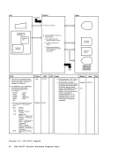
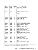
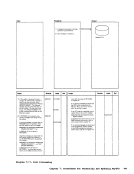
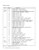
Overview of the
Format/Allocate Program•••• 66
The For.at Function•••••••• 67
The Allocate Function•••••• 68 Overview of the Directory
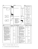
Progra••••••••••••••••••••• 83 DMKDIR Control Statement
Processing••••••••••••••••• 84
DMKDIRControl Statement
Processing••••••••••••••••• 85 DMKDIR Control Statement
processing••••••••••••••••• 86
Directory Exit••••••••••••• 87
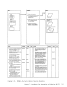
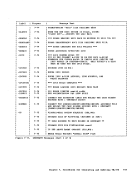
overview of the DDR
program•••••••••••••••••••• 95
DDRProgram Control Statement processing ••••••• 96
TheDump Function •••••••••• 97
The Restore Function••••••• 98
TheCopy Function •••••••••• 99
ThePrint Function •••••••• 100 The Type Function ••••••••• l01 The IVP EXEC Procedure •••• 115 Overview of the IVPX EXEC Procedure •••••••••••• 116
Test Procedure 1•••••••••• 117
Test Procedure 2•••••••••• 118
InstallationVerification Procedure Error
Processing•••••••••••••••• 119
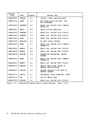
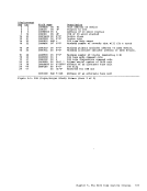
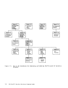
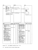
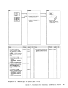
Diagram 7-1.Overview of the Assembler Update Prccedure •••••••••• 131
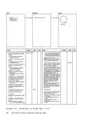
Diagram 7-2. Initialization of theVMFASM Procedure •••••••••• 132
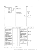
Diagram 7-3. Assembling Portion of theVMFASM Procedure •••••••••• 133
xIBM VM/370 Service Routines Program Logic
Diagram 7-4.
tiagram 7-5.tiagram 7-6.
Diagram 7-7.
Diagram 7-8.
Diagram 7-9.
Diagram7-10. Diagram 7-11.
Diagram 7-12.
Diagram 7-13.
Diagram 7-14.
Diagram 7-15.
Diagram 8-1.Diagram 9-1.
Diagram 9-2.Diagram 9-3.
Diagram 9-4.
Diagram 9-5.
Diagram 9-6.
Diagram 9-7.
Diagram 9-8.
Diagram 9-9.
Diagram 1C-1. Diagram 10-2. tiagram 1C-3. Diagram 1C-4. DiagJam 1C-5.
Diagram 1C- 6.
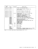
Diagram1C-7. Diagram lC-8. Diagram 10-9. The VMFDATE Program ••••••• 134
Overview of theUpdate (DMSUPD) Program •••••••••• 135 Operand and Option Checking •••••••••••••••••• 136 Multiple Update Procedure.137 Control Record Processing.138 Single Update Procedure ••• 139
InsertingUpdates ••••••••• 140 Exit processing ••••••••••• 141
The Nucleus Load program•• 142 VMFMAC--Macro Library Creation program •••••••••• 143
The GENERATE procedure•••• 144
Generating aCP System •••• 147 DMKSSP--The Starter System •••••••••••••••••••• 165 DMSNCP--SAVENCP Command processor ••••••••••••••••• 171 DMSNCP--Building the CCPARM List ••••••••••••••• 172 DMSGRN--Overview of the GEN3705 Co.mand processor ••••••••••••••••• 173
DMSGRN--Generating the3705 Assembler Files •••••• 174 DMSGRN--Generating the
Link/Edit Files••••••••••• 175 DMSARN--ASM3705 Command Processor (for the NCP/VS Release 2 and 3
Assembler)•••••••••••••••• 176 DMSARX--ASM3705 Command Processor (for the NCP/VS Release 4 Assembler) •••••• 177 DMSLKD--LKED Command Processor ••••••••••••••••• 179 DMKRND--NCFDUMP Command Processor ••••••••••••••••• 180 Overview of the ZAP program ••••••••••••••••••• 197 ZAP Initialization and Control Record
processing•••••••••••••••• 198 DUMP Contrel Record
processing•••••••••••••••• 199 NAME and BASE Centrol Record Processing ••••••••• 200 VER/VERIFY or REP and END Control Record
processing•••••••••••••••• 201 Opening the File •••••••••• 202 Finding the CSECT ••••••••• 203 Reading the Text •••••••••• 204 Printing the Dump ••••••••• 205 Diagram 11-1. DMSIFC •••••••••••••••••••• 213
Diagram 11-2.DMSREA •••••••••••••••••••• 214
Diagram 12-1.DMKMSS Initialization ••••• 225
Diagram 12-2.DMKMSS Processing ••••••••• 226
Diagram 1-2.
Diagram 1-3.
Diagram 2-1.
Diagram 2-2.
Diagram 2-3.
Diagram 2-4.
Diagram 2-5.
Diagram 2-6.
Diagram 2-7.
Diagram 2-8.
Diagram 2-9.
Diagram
Diagram 2-12.
Diagram 3-1.
Diagram 3-2.
Diagram 3-3.
Diagra. 4-1.
Diagram 4-2.
Diagram 4-3.
Diagram 4-4.
Diagram 4-5.
Diagram 5-1 ..
Diagram 5-2.
Diagram 5-3.
Diagram 5-4.
Diagram 5-5.
Diagram 5-6.
Diagram 5-7.
Diagram 6-1.
Diagram 6-2.
Diagram 6-3.
Diagram 6-4.
Diagram 6-5.
Overview of
Initialization
Initializing a
Load Map
Program
Operator Initiated Routine
Information
Format and
Overview of the
Format/Allocate Program
The For.at Function
The Allocate Function
Progra
Processing
DMKDIR
Processing
processing
Directory Exit
overview of the DDR
program
DDR
The
The Restore Function
The
The
Test Procedure 1
Test Procedure 2
Installation
Processing
Diagram 7-1.
Diagram 7-2. Initialization of the
Diagram 7-3. Assembling Portion of the
x
Diagram 7-4.
tiagram 7-5.
Diagram 7-7.
Diagram 7-8.
Diagram 7-9.
Diagram
Diagram 7-12.
Diagram 7-13.
Diagram 7-14.
Diagram 7-15.
Diagram 8-1.
Diagram 9-2.
Diagram 9-4.
Diagram 9-5.
Diagram 9-6.
Diagram 9-7.
Diagram 9-8.
Diagram 9-9.
Diagram 1
Diagram 1
Diagram
Overview of the
Inserting
The Nucleus Load program
The GENERATE procedure
Generating a
DMSGRN--Generating the
Link/Edit Files
Assembler)
processing
processing
processing
Diagram 11-2.
Diagram 12-1.
Diagram 12-2.