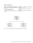
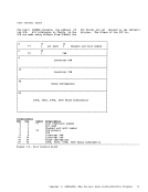
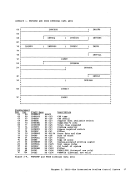
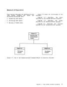
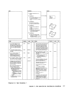
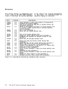
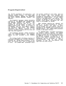
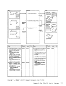
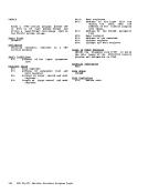
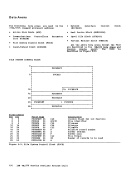
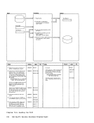
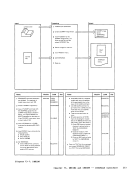
Method of Operation
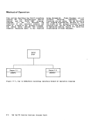
This section describes theCftS modules that
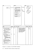
provide the co•• ands to generate the 3704/3705 control progra.s. Diagrams describe the functions perforaed by each of
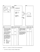
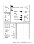
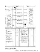
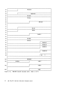
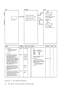
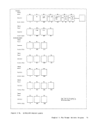
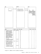
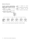
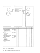
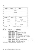
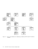
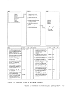
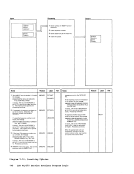
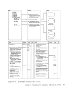
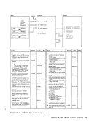
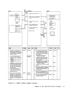
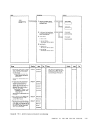
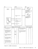
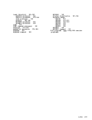
the co.mand processors. Figure 9-1 shows
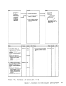
the relationships between these diagra.s.Diagram 9-1 describes the SAVENCP co •• and, which saves an image of the 3704/3705 control program so that it can
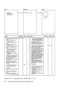
later be loaded. Diagra. 9-2 shows howCCPARft is built.
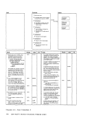
Diagrams 9-3, 9-4, and 9-5 describe theGEN3705 com.and, which generates a series
ofcommands to assemble, link edit, and
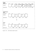
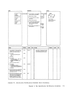
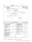
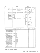
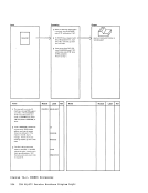
load the3704/3705 control program. Diagram 9-1 Diagram 9-3 Diagram 9-6 DMSNCP - DMSGRN - DMSARN - SAVENCP Overview of the ASM3705 Command GEN3705 Command Processor Command Processor Processor I Diagram 9-2 Diagram 9-4 Diagram 9-5 DMSNCP - DMSGRN - DMSGRN - Building the Generati ng the Generating the CCPARM List 3705 Assembler Link Edit Files Files tiagrams 9-6 ASft3705 co.mand, between e!s and eIIKAS! or CWAXOO). and 9-7 describe the
which is an interface
theICP/VS Assembler Diagram 9-8 describes the LKED co •• and,
which is an interface bEtweenCftS and the as/VS1 Linkage Editor.
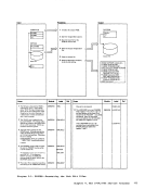
Diagra. 9-9 describescom.and, which prints a 37C4/3705 storage.
Diagram 9-7 Diagram 9-8DMSARX - DMSLKD - ASM3705 LKED Command Command Processor
ProcessorRCPDU!!F of the
Diagram 9-9
DMKRND -NCPDUMP Command Processor
Figure 9-1. Key to the3704/3705 Service programs Bethod of Operation Diagrams 170 IBM VM/370 Service Routines Program Logic
This section describes the
provide the co
the co.mand processors. Figure 9-1 shows
the relationships between these diagra.s.
later be loaded. Diagra. 9-2 shows how
Diagrams 9-3, 9-4, and 9-5 describe the
of
load the
which is an interface
the
which is an interface bEtween
Diagra. 9-9 describes
Diagram 9-7 Diagram 9-8
Processor
Diagram 9-9
DMKRND -
Figure 9-1. Key to the