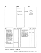
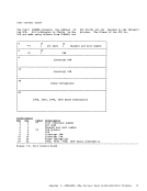
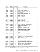
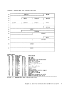
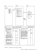
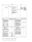
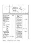
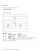
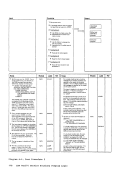
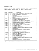
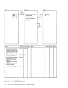
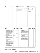
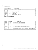
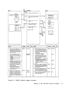
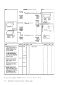
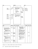
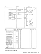
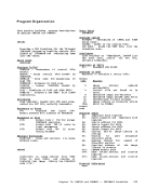
Control
Cards
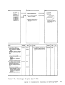
Notes Module
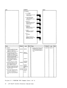
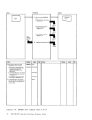
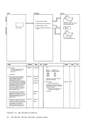
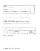
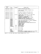
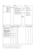
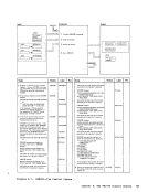
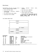
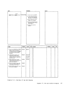
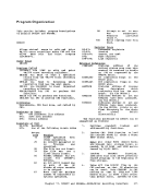
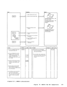
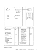
1 The general registers are cleared and
set to X'FF' and the program enters
a wait state with X'FFFF' in the
address field of the
virtual machine console and the input
statement is read. The control cards
may be read from a
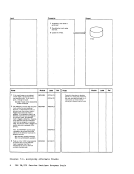
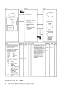
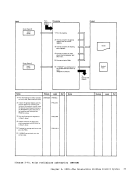
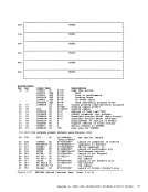
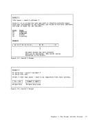
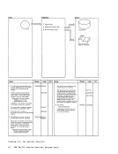
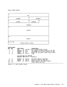
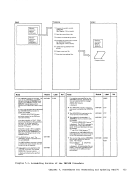
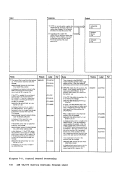
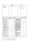
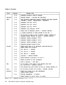
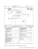
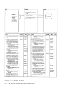
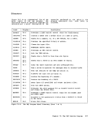
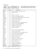
2 Next, the
at
pointer to a field and the length of
the field in registers
LENGTH, respectively, and an indica-
tion of the field type in location
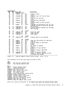
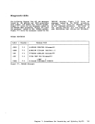
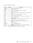
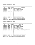
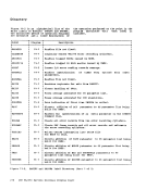
byte switch with the
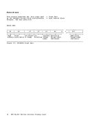
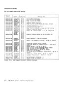
X'50' Control statement error
X'40' Bypass
X'10' First control statement
has been read
x'oa' Operator found
X'04' Keyword found
X'02' Parameter found
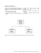
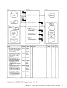
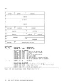
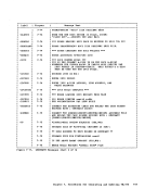
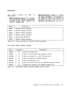
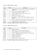
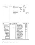
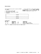
Processing
the
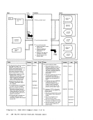
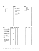
2 Analyze the control cards.
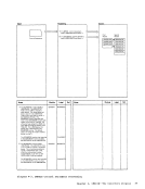
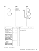
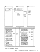
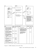
3
the disk.
4
alternate track.
details.)
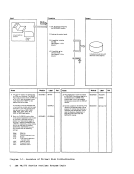
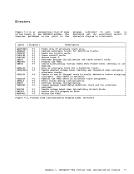
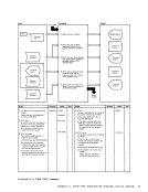
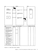
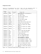
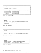
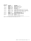
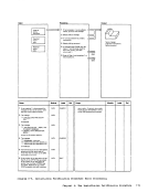
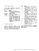
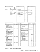
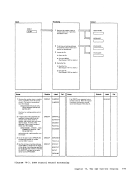
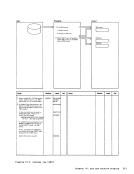
START 3 The initialization routine is entered
at VOLCHK if the
be checked and at GEN5E if the
volume
Initialization starts with the
routine.
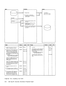
assigned.
requested, the CKVOLLBL routine
does the checking. Assignment of
GETALTX routine.
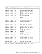
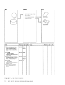
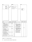
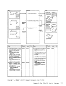
Module
GEN5E
6
Ref