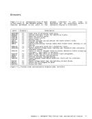
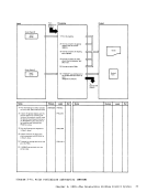
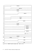
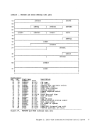
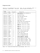
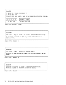
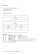
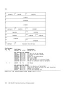
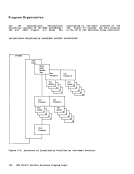
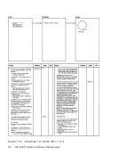
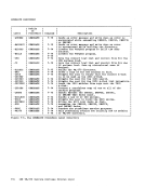
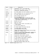
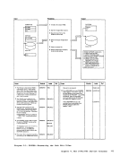
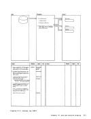
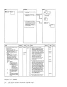
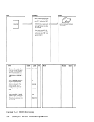
REG 1
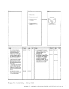
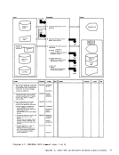
List of
optional
fileid from
the
Initialize.
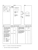
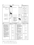
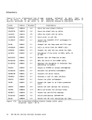
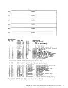
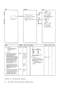
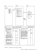
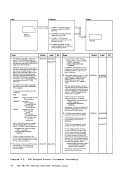
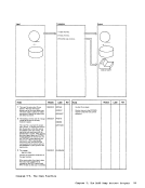
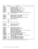
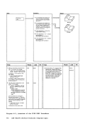
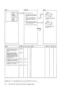
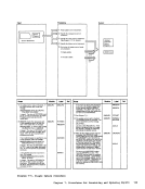
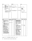
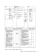
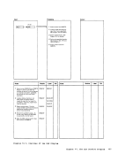
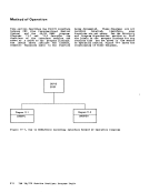
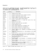
3 Determine source of control card
parameters.
REG 1
Control
Parameters
control card file.
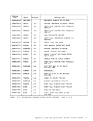
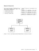
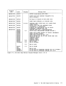
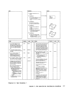
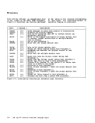
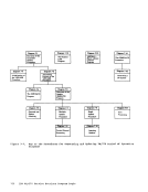
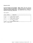
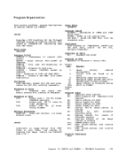
1 The initialization procedures include:
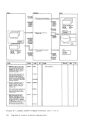
11-1
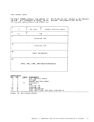
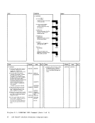
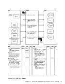
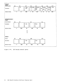
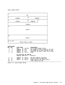
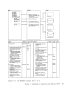
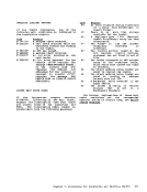
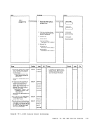
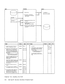
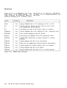
functions.
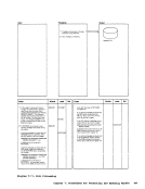
cause
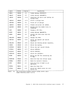
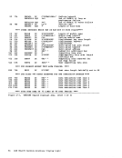
to load LINK and
validity by examining processor
identity.
but if valid, erase error records
from the error recording cylinders
then initialize
beginning of the error recording
cylinders.)
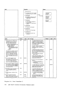
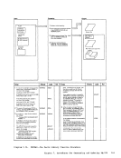
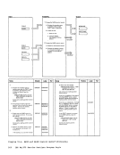
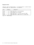
to be entered in TEXT files.
and goes to terminal to read addition-
al control parameters) .
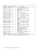
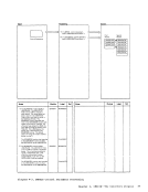
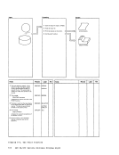
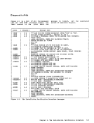
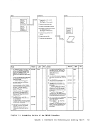
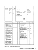
3 Determine where control parameters
cepted and simulated so they appear
4 Set up to read parameters.
storage for
to EREP. Read control parameters,
simulated by
errors.
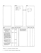
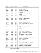
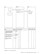
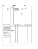
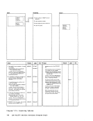
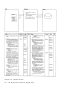
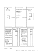
5
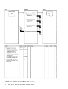
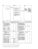
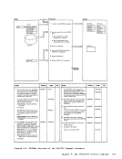
parameters, type an error message. CLEARRTN
subroutine to erase error records from
the
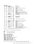
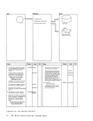
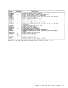
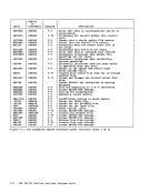
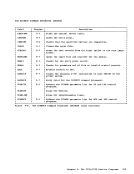
Subroutines handle each parameter
information:
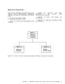
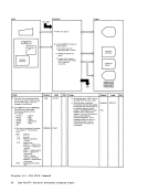
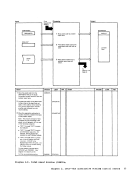
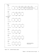
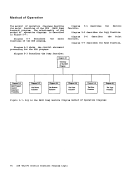
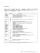
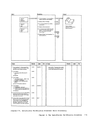
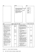
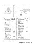
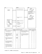
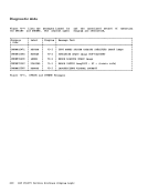
Diagraa 11-1.
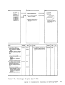
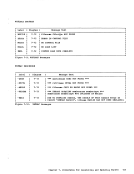
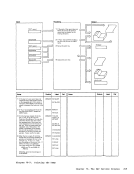
HCLEARF
HCLEAR
HTERM