Pseudo Timer
Pseudo Timer Start I/O
Pseudo Timer DIAGNOSE
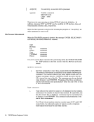
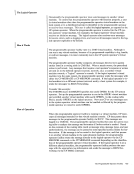
The pseudo timer is a specialVM/SP timing facility. It provides 24 or 32 bytes of
time and date information in the format shown in Figure 28.
StartI/O Diagnose
<------8 bytes -------> <--- 8 bytes >
orVIRTCPU I TOTCPU VIRTCPU TOTCPU Figure 28. Fonnats of Pseudo Timer Infonnation
The first eight-byte field is the date, in EBCDIC, in the form
Month/Day-of-Month/Year. The next eight-byte field is the Time of Day in
Hours:Minutes:Seconds. TheVIRTCPU and TOTCPU fields contain virtual
processor and total processor time used. The units in which the processor times are
expressed and the length of the fields depend upon which of two methods is used
for interrogating the pseudo timer.
The pseudo timer can be interrogated by issuing a STARTI/O to the pseudo timer
device, which is device type TIMER, and is usually at device addressOFF. No I/O interrupt is returned from the SIO. The address in virtual storage where the timer
information is to be placed is specified in the data address portion of the CCW
associated with theSIO. This address must not cross a page boundary in the user's
address space. If this method is used, the virtual processor and the total processor
times are expressed as full words in high resolution interval timer units.One unit is
13 microseconds.
The pseudo timer can also be interrogated by issuing DIAGNOSE with an opera
tion code of C, as described under"DIAGNOSE Instruction in a Virtual Machine." If this method is used, the virtual and total processor times are expressed as
doublewords in microseconds.
Timers in a Virtual Machine207
Pseudo Timer Start I/O
Pseudo Timer DIAGNOSE
The pseudo timer is a special
time and date information in the format shown in Figure 28.
Start
<------
or
The first eight-byte field is the date, in EBCDIC, in the form
Month/Day-of-Month/Year. The next eight-byte field is the Time of Day in
Hours:Minutes:Seconds. The
processor and total processor time used. The units in which the processor times are
expressed and the length of the fields depend upon which of two methods is used
for interrogating the pseudo timer.
The pseudo timer can be interrogated by issuing a START
device, which is device type TIMER, and is usually at device address
information is to be placed is specified in the data address portion of the CCW
associated with the
address space. If this method is used, the virtual processor and the total processor
times are expressed as full words in high resolution interval timer units.
13 microseconds.
The pseudo timer can also be interrogated by issuing DIAGNOSE with an opera
tion code of C, as described under
doublewords in microseconds.
Timers in a Virtual Machine