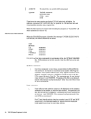
The ACCEPT subfunction reads data that CP has directed to a logical device. It is
invoked after the virtual machine that created the logical device is notified via
external interrupt that output data is to be processed. Upon invocation register
Rx+ 1 must contain the data buffer address and register Ry+ 1 the buffer length. If
the data buffer supplied was too short to contain the data, the subfunction returns
the required buffer size in register Ry and no data is moved. This action can be
overridden by setting an indicator in the length register (bit zero in Ry+ 1 set to 1)
when the subfunction is invoked. In this case, the data is be moved to the short
buffer and a CC=O, RC=2 is sent. The system moves the next portion of the data
on the nextACCEPT. Upon successful completion of subfunction processing, the
data length is returned in Ry, and the data buffer contains the CCWOP code in its
first byte and data in the remaining buffer space.PRESENT: DIAGNOSE CODE X'7C' SUBFUNCTION CODE X'0003'
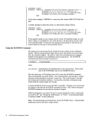
ThePRESENT subfunction passes input data to CP. The location of the data is
described by an address or a complemented address in register Rx+ 1. If the regis
ter contains an address, it is the address of a data buffer 4096 bytes or less in
length. In this case, register Ry+ 1 contains the length of that data buffer. If regis
ter Rx + 1 contains a complemented address, it is the address of a list that describes
a data stream occupying multiple data buffers and/or greater than 4096 bytes in
length. In this case, register Ry+ 1 is not used to describe the data length. Howev
er, in either case, a high-order bit of 1 in register Ry+ 1 indicates that the response
is to a READ BUFFER command. Data format is the same as that produced by a
local display control unit in response to a READMODIFIED channel command.
If a list is used to describe the data, the list must be in the format:
LengthSEGI Address SEGI Length SEG2 Address SEG2 Length SEGn1( Address SEGn *Last entry indicated by a 1 in bit zero of its length field.
The list must start on a fullword boundary. Each entry consists of two full word
fields that describe the length and location of sequential segments of a data stream.
A single entry list may be used to describe a single data buffer greater than 4096
bytes in length. Neither the list nor the data may be modified before transfer of
the data has completed.-An external interrupt signals completion of data transfer.
TERMINATE:DIAGNOSE CODE X'7C' SUBFUNCTION X'0004'
The TERMINATE subfunction notifiesCP to drop a specific logical device. If the
logical device is the console of a virtual machine, the virtual machine is placed inFORCE DISCONNECT state. If the logical device is DIALed to a virtual
machine, it is detached from that virtual machine. If an input or output operation is
being processed, it is terminated with a unit check and intervention required.
TERMINATE (ALL):DIAGNOSE CODE X'7C' SUBFUNCTION X'0005' DIAGNOSE Instruction in a Virtual Machine 263
invoked after the virtual machine that created the logical device is notified via
external interrupt that output data is to be processed. Upon invocation register
Rx+ 1 must contain the data buffer address and register Ry+ 1 the buffer length. If
the data buffer supplied was too short to contain the data, the subfunction returns
the required buffer size in register Ry and no data is moved. This action can be
overridden by setting an indicator in the length register (bit zero in Ry+ 1 set to 1)
when the subfunction is invoked. In this case, the data is be moved to the short
buffer and a CC=O, RC=2 is sent. The system moves the next portion of the data
on the next
data length is returned in Ry, and the data buffer contains the CCW
first byte and data in the remaining buffer space.
The
described by an address or a complemented address in register Rx+ 1. If the regis
ter contains an address, it is the address of a data buffer 4096 bytes or less in
length. In this case, register Ry+ 1 contains the length of that data buffer. If regis
ter Rx + 1 contains a complemented address, it is the address of a list that describes
a data stream occupying multiple data buffers and/or greater than 4096 bytes in
length. In this case, register Ry+ 1 is not used to describe the data length. Howev
er, in either case, a high-order bit of 1 in register Ry+ 1 indicates that the response
is to a READ BUFFER command. Data format is the same as that produced by a
local display control unit in response to a READ
If a list is used to describe the data, the list must be in the format:
Length
The list must start on a fullword boundary. Each entry consists of two full word
fields that describe the length and location of sequential segments of a data stream.
A single entry list may be used to describe a single data buffer greater than 4096
bytes in length. Neither the list nor the data may be modified before transfer of
the data has completed.
TERMINATE:
The TERMINATE subfunction notifies
logical device is the console of a virtual machine, the virtual machine is placed in
machine, it is detached from that virtual machine. If an input or output operation is
being processed, it is terminated with a unit check and intervention required.
TERMINATE (ALL):