Conversely, pressing the PAl key or issuing the "BEGIN" command returns con
trol to the programmable operator facility. From this environment, issuing SET
DEBUGOFF causes the programmable operator facility to return to its normal
function of trapping messages.
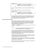
The Action Routine Interface
Action Routine Call Interface
Action routines are loaded by the programmable operator facility as CMS nucleus
extensions. As a result, they must be invoked by the programmable operator facili
ty as CMS commands via SVC 202. Also, addresses cannot be resolved between
separate nucleus extensions; they must be passed dynamically if they are desired.
Action Routine Parameter Interface
An installation can write additional action routines in Basic Assembler Language.
Action routines may also be written as EXECs. Programs written in Basic Assem
bler Language can access the parameter list built by the programmable operator
facility. (The programmable operator parameters are available in a different fash
ion for EXEC action routines--see below.) The parameter list contains a list of
addresses pointing to data that may be significant to the action routine invoked.
The programmable operator facility then passes the address of the list as a parame
ter when it invokes the required action routine. See VM /SP Data Areas and Con
trol Block Logic, Volume 2 for descriptions of the DSECTs mentioned below.
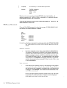
The register conventions used for invoking an action routine are:
Register 1 points to a list of eight-byte tokens (CMS PLIST) containing the
following information:TOKEN 1 Contains the command name (action routine name). TOKEN 2 Contains two fullwords. These fullwords contain the
following:
Fullword 1 -
Fullword 2-
Contains the address of thePROP common
area as described by thePROPCOM DSECT.
Contains the address of a list of addresses that
point to data that may be needed by the
action routine. This list is described by the
PARMLIST DSECT.TOKEN 3 Contains eight X'FF's to mark the end of the parameter list.
Register 13 points to a standard as eighteen word save area.
Register 14 points to the address that receives control when the action rou
tine completes processing, i.e. the address to which the action routine must
return control.
Register 15 points to the action routine entry point and may be used as a
base register.
The Programmable Operator Facility 453
trol to the programmable operator facility. From this environment, issuing SET
DEBUG
function of trapping messages.
The Action Routine Interface
Action Routine Call Interface
Action routines are loaded by the programmable operator facility as CMS nucleus
extensions. As a result, they must be invoked by the programmable operator facili
ty as CMS commands via SVC 202. Also, addresses cannot be resolved between
separate nucleus extensions; they must be passed dynamically if they are desired.
Action Routine Parameter Interface
An installation can write additional action routines in Basic Assembler Language.
Action routines may also be written as EXECs. Programs written in Basic Assem
bler Language can access the parameter list built by the programmable operator
facility. (The programmable operator parameters are available in a different fash
ion for EXEC action routines--see below.) The parameter list contains a list of
addresses pointing to data that may be significant to the action routine invoked.
The programmable operator facility then passes the address of the list as a parame
ter when it invokes the required action routine. See VM /
trol Block Logic, Volume 2 for descriptions of the DSECTs mentioned below.
The register conventions used for invoking an action routine are:
Register 1 points to a list of eight-byte tokens (CMS PLIST) containing the
following information:
following:
Fullword 1 -
Fullword 2-
Contains the address of the
area as described by the
Contains the address of a list of addresses that
point to data that may be needed by the
action routine. This list is described by the
PARMLIST DSECT.
Register 13 points to a standard as eighteen word save area.
Register 14 points to the address that receives control when the action rou
tine completes processing, i.e. the address to which the action routine must
return control.
Register 15 points to the action routine entry point and may be used as a
base register.
The Programmable Operator Facility 453