Nucleus Load Map
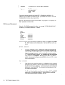
Load Map
D T2CF158.10 «<--Display where the interrupt happened
2CF150C01858CO DOF81BFF 000007F6 50C3D9C1 * ..... 8 ..... 6&CRA* 2CF160 E2C8189F 47FOC1E2 45EOAAB8 078745EO *SH ... OAS ........ * B 2CF15A «<--Continue as if no interrupt happened
Each time the eMS resident nucleus is loaded on a DASD and an IPL can be per
formed on that DASD, a load map is produced as a printer spool file. Save this
load map. It lists the virtual storage locations of nucleus-resident routines and
work areas. Transient modules are not included in this load map. When debugging'
eMS, you can locate routines using this map. For information on obtaining a load
map, see"Generating a eMS Nucleus" in the VM/SP Installation Guide.
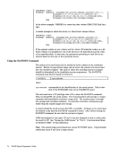
The load map of a disk-resident command module contains the location of control
sections and entry points loaded into storage. It may also contain certain messages
and card images of any invalid cards or replace cards that exist in the loaded files.
The load map is contained in the third record of theMODULE file.
This load map is useful in debugging. When using the Debug environment to ana
lyze a program, use the program's load map to help in displaying information.
There are two ways to get a load map.
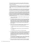
1. When loading relocatable object code into storage, make sure that the MAP
option is in effect when the LOAD command is issued. Since MAP is the
default option, just be sure thatNOMAP is not specified. A load map is then
created on the primary disk each time aLOAD command is issued.
2. When generating the absolute image form of files already loaded into storage,
make sure that the MAP option is in effect when theGENMOD command is
issued. Since MAP is the default option, just be sure thatNOMAP is not spec
ified. Issue theMODMAP command to type the load map associated with the
specifiedMODULE file on the terminal. The format of the MODMAP com
mand is:I MODmap
where:
filename
filename
is the module whose map is to be displayed. The file type must beMODULE. Reading eMS Abend Dumps
If an abend dump is desired when eMS abnormally terminates, the terminal opera
tor must enter theDEBUG command and then the DUMP subcommand. The
dump formats and prints:
General registers
Debugging WitheMS 529
Load Map
D T2CF158.10 «<--Display where the interrupt happened
2CF150
Each time the eMS resident nucleus is loaded on a DASD and an IPL can be per
formed on that DASD, a load map is produced as a printer spool file. Save this
load map. It lists the virtual storage locations of nucleus-resident routines and
work areas. Transient modules are not included in this load map. When debugging'
eMS, you can locate routines using this map. For information on obtaining a load
map, see
The load map of a disk-resident command module contains the location of control
sections and entry points loaded into storage. It may also contain certain messages
and card images of any invalid cards or replace cards that exist in the loaded files.
The load map is contained in the third record of the
This load map is useful in debugging. When using the Debug environment to ana
lyze a program, use the program's load map to help in displaying information.
There are two ways to get a load map.
1. When loading relocatable object code into storage, make sure that the MAP
option is in effect when the LOAD command is issued. Since MAP is the
default option, just be sure that
created on the primary disk each time a
2. When generating the absolute image form of files already loaded into storage,
make sure that the MAP option is in effect when the
issued. Since MAP is the default option, just be sure that
ified. Issue the
specified
mand is:
where:
filename
filename
is the module whose map is to be displayed. The file type must be
If an abend dump is desired when eMS abnormally terminates, the terminal opera
tor must enter the
dump formats and prints:
General registers
Debugging With