Appendix A. System/370 Information
Control Registers
o
1
2
3
4
5
6
7
8
910 11
12
13
14
15
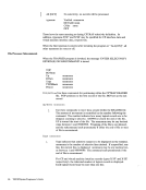
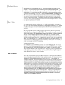
The control registers are used to maintain and manipulate control information that
resides outside thePSW. There are sixteen 32-bit registers for control purposes.
The control registers are not part of addressable storage.
At the time the registers are loaded, the information is not checked for exceptions,
such as invalid segment-size or page-size code or an address designating an una
vailable or a protected location. The validity of the information is checked and the
errors, if any, indicated at the time the information is used.
Figure 72 is a summary of the control register allocation and Figure 73 on page
538 lists the facility associated with each control register.
Figure 74 on page 541 is a description of the Ee (Extended Control)PSW. (--------------------------- 32 bits --------------------------> SYSTEM CONTROL TRANSL. CONTROL EXTERNAL-INTERRUPTION NASKS SEGM-TBL LENGTH SEGMENT-TABLE-ORIGIN-ADDRESS! CHANNEL MASKS HARDWARE ASSIST CONTROLS MONITOR MASKS PER EVENT MASKS PER GR ALTERATION MASKS PER STARTING ADDRESS PER ENDING ADDRESS ERROR-RECOVERY CONTROL & MASKS MCEL ADDRESS Figure 72. Control Register Allocation
Appendix A. System/370 Information 537
Control Registers
o
1
2
3
4
5
6
7
8
9
12
13
14
15
The control registers are used to maintain and manipulate control information that
resides outside the
The control registers are not part of addressable storage.
At the time the registers are loaded, the information is not checked for exceptions,
such as invalid segment-size or page-size code or an address designating an una
vailable or a protected location. The validity of the information is checked and the
errors, if any, indicated at the time the information is used.
Figure 72 is a summary of the control register allocation and Figure 73 on page
538 lists the facility associated with each control register.
Figure 74 on page 541 is a description of the Ee (Extended Control)
Appendix A. System/370 Information 537